


5-27
INSTALLATION-DK 16 KSU & PCB
SECTION 100-816-205
MARCH 1993
Program 41
Assigns stations access to CO lines (outgoing
only).
Program 42-0, 1-8
Assigns behind PBX/CENTREX operation to
each CO line.
Programs 45 ~ 48
Defines Toll Restrictions for any CO line.
Programs 50 ~ 56
Defines Least Cost Routing using CO lines.
Program 78
Assigns special ringing of CO lines: Night Ring
Over Page, DISA, IMDU.
Programs 81 ~ 89
Assigns CO lines to ring selected stations.
Assigns Delayed Ringing to any CO line.
Program 93
Assigns names to CO lines.
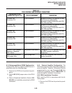
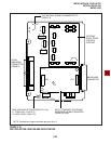
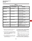
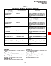
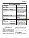
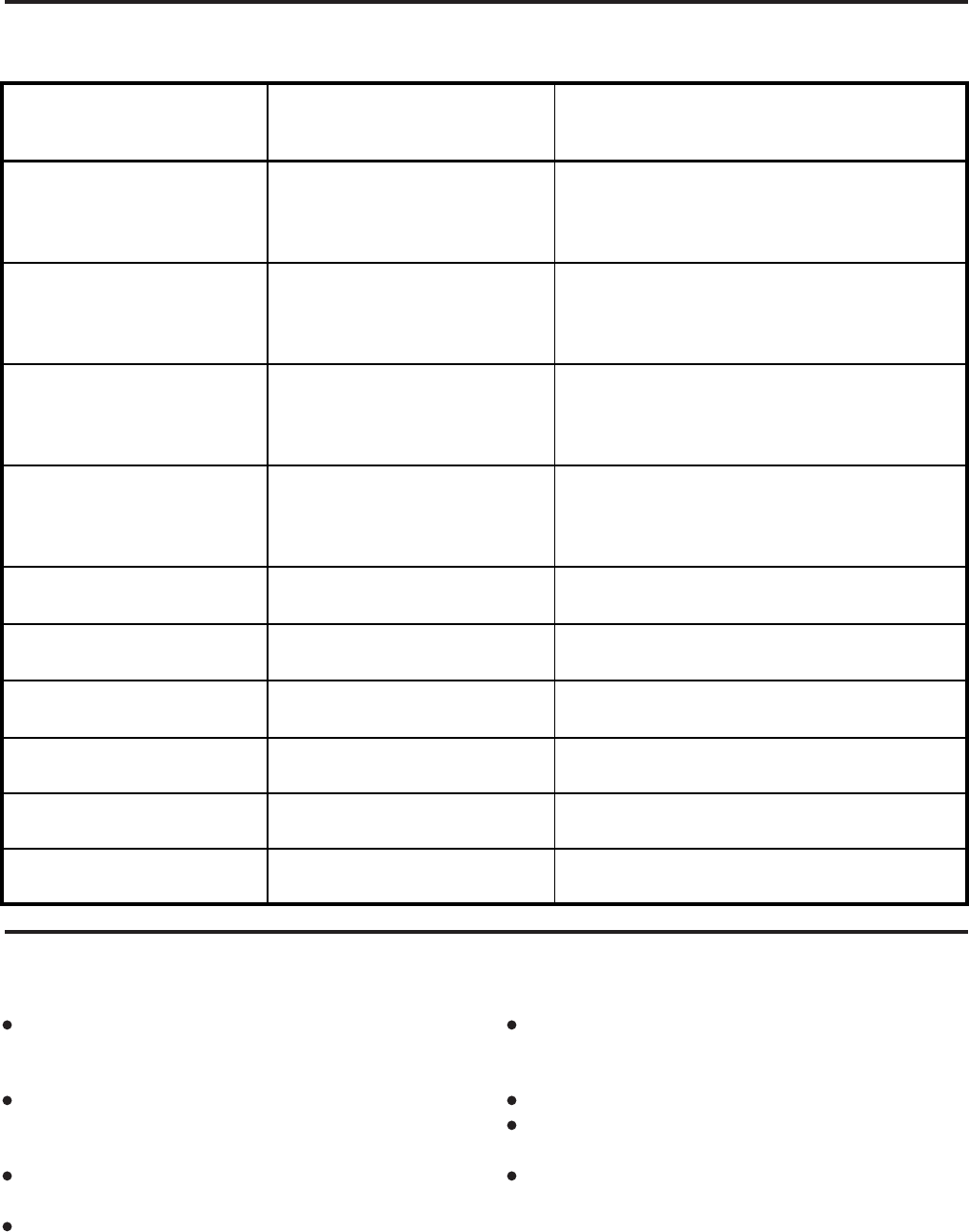
TABLE 5-E
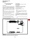
PCOU CONTROLS, INDICATORS, AND INTERFACE CONNECTORS
CONTROL/INDICATOR/
CONNECTOR
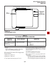
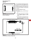
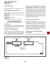
(Figure 5-17)
TYPE OF COMPONENT DESCRIPTION
CO Line Circuit 1
Indicator CD112
Red LED
Lights to indicate CO line circuit 1 is in
operation (NOTE: CO line indicator will
not light unless PCOU is connected to
a CO).
J1 Connector
Modular connector
Interface connector for CO line circuits
1 and 2.
CO Line Circuit 2
Indicator CD212
Red LED
Lights to indicate CO line circuit 2 is in
operation (NOTE: CO line indicator will
not light unless PCOU is connected to
a CO).
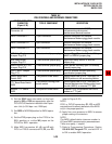
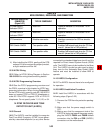
CO Line Circuit 3
Indicator CD312
Red LED
Lights to indicate CO line circuit 3 is in
operation (NOTE: CO line indicator will
not light unless PCOU is connected to
a CO).
CO Line Circuit 4
Indicator CD412
Red LED
Lights to indicate CO line circuit 4 is in
operation (NOTE: CO line indicator will
not light unless PCOU is connected to
a CO).
J2 Connector
Modular connector
Interface connector for CO line circuits
3 and 4.
PAD Switch SW101
Two-position slide
Enables 3dB signal level drop for CO line
circuit 1.
PAD Switch SW201
Two-position slide
Enables 3dB signal level drop for CO line
circuit 2.
PAD Switch SW301
Two-position slide
Enables 3dB signal level drop for CO line
circuit 3.
PAD Switch SW401
Two-position slide
Enables 3dB signal level drop for CO line
circuit 4.