


5-34
INSTALLATION-DK 16 KSU & PCB
SECTION 100-816-205
MARCH 1993
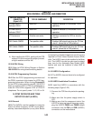
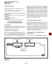
tical to the PCOU and KCDU CO line circuits. The
KCOU also has four PAD (3 dB) switches—SW400,
SW425, SW450, and SW475—to reduce exces-
sive loudness caused by a nearby CO or PBX
telephone system. For wiring and programming
considerations, see the PCOU instructions in Para-
graph 8. The Base Unit circuits are fixed and are
assigned to Base Unit virtual equipment slots as
follows: 8-digital station circuit to slot 01, 4-CO line
circuits (KCOU) to slot 02, and 4 standard tele-
phone circuits (KSTU) to slot 3.
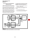
15.20 Digital Telephone Circuits
15.21 The eight digital telephone circuits that come
standard with the system are integrated into the
motherboard in the Base Unit. These circuits are
indentical to the digital circuits found on the PDKU
and KCDU. The motherboard does not have to be
configured for the digital circuits to operate. For
wiring and programming considerations, see the
PDKU instructions in Paragraph 7.
15.30 Base Unit CO Line/Digital Station
Circuit Wiring
15.31 Refer to Section 100-816-208 for details.
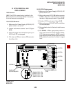
14.30 K4RCU Wiring
14.31 The K4RCU does not require any wiring.
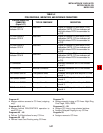
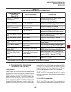
14.40 K4RCU Programming Overview
14.41 The following parameters may be specified:
Program 03
Enter code 92 for Slot 00 if K4RCU is installed.
Program 12
Set K4RCU release time.
Program 15
Sets K4RCU operation after CO line flash.
15 BUILT-IN CO LINE AND
DIGITAL TELEPHONE CIRCUITS
15.00 General
15.01 As mentioned in Paragraph 2, the Base Unit
comes standard with four CO lines and eight digital
telephone circuits already installed.
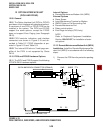
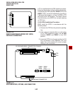
15.10 Built-in CO Line Circuits
15.11 The four standard loop start CO line circuits
are on a printed circuit board (PCB) called the
KCOU, which is installed on the motherboard at the
factory (Figure 5-23). The KCOU circuits are iden-
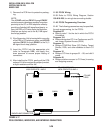
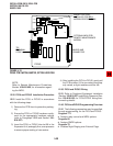
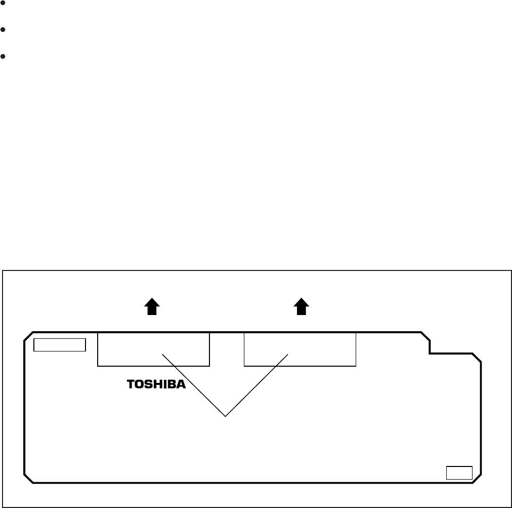
FIGURE 5-22
K4RCU PCB
VERSION
P602A P602B
P2A (BASE UNIT) P2B (BASE UNIT)
CONNECTORS