


8-20
INSTALLATION-WIRING DIAGRAMS
SECTION 100-816-208
MARCH 1993
W-Bl
Bl-W
W-O
O-W
W-G
G-W
W-Br
Br-W
W-S
S-W
R- Bl
Bl-R
R-O
O-R
R-G
G-R
R-Br
Br-R
R-S
S-R
Bk-Bl
Bl-Bk
Bk-O
O-Bk
Bk-G
G-Bk
Bk-Br
Br-Bk
Bk-S
S-Bk
Y-Bl
Bl-Y
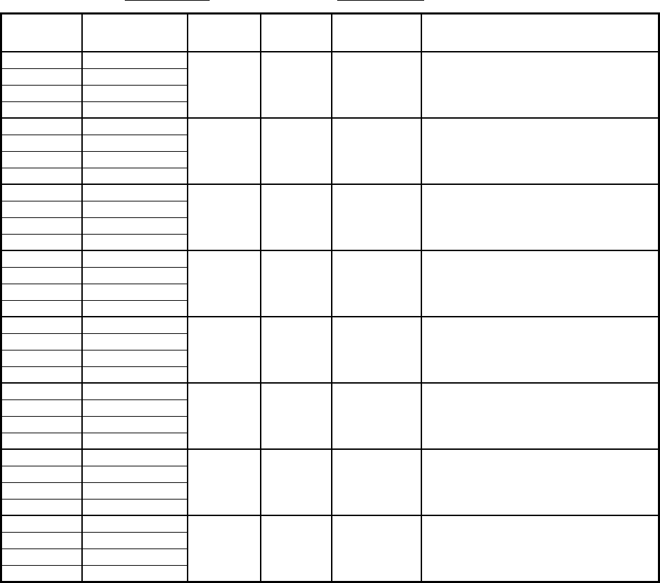
COLOR
CODE
VT
VR
DT
DR
ELECTRONIC TELEPHONE/
DEVICE LOCATION
VT
VR
DT
DR
VT
VR
DT
DR
VT
VR
DT
DR
VT
VR
DT
DR
VT
VR
DT
DR
VT
VR
DT
DR
VT
VR
DT
DR
DESIGNATION
CKT
NUMBER
PORT
NUMBER
INTERCOM
NUMBER
1
2
3
4
5
6
7
8
MDF BLOCK NO. SLOT NO.
1
2
2
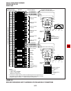
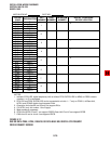
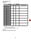
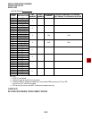
NOTES:
1. Indicate if BGM or electronic telephone is connected (see Program 10-2 and 19); BGM connects to VT
and VR, circuit 3 only (DT and DR not used).
2. Indicate if electronic telephone or HDSS console.
3. OCA wirin
g
not shown, see MDF-to-electronic telephone wirin
g
.
FIGURE 8-16
DK16 PEKU STATION/MDF CROSS CONNECT RECORD