


INSTALLATION-DK8 KSU & PCB
SECTION 100-816-204
MARCH 1993
4-16
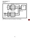
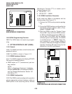
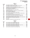
J1J2
RIGHT
Maintenance Terminal (TTY) or modem; and in
System Prograrm 10-3:
LED 04 ON — TTY
LED 04 OFF — SMDR
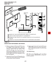
11.30 QSMU Installation Procedure
11.31 Install the QSMU in accordance with the
following steps (See Figure 4-7):
1) Remove the PCB from its protective packag-
ing.
2) Ensure the QSMU has been configured for the
appropriate program options (refer to Para-
graphs 11.10 and 11.20).
3) Slide the QSMU under the "System Frame
Ground Bar", align and insert QSMU connec-
tor J2 into motherboard connector J20, ensur-
ing the side of the QSMU with the modular
connector goes on the right side. (The QSMU
is not silkscreened “
➝
RIGHT”.) Apply firm,
even pressure to ensure proper mating of
connectors. Make sure the edge of the QSMU
opposite connector J2 snaps firmly into the
standoffs on the KSU motherboard.
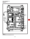
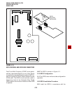
FIGURE 4-13
QSMU CONTROLS AND INTERFACE CONNECTORS
10.40 QCNU Programming Overview
10.41 The QCNU does not require any program-
ming.
11 OPTION INTERFACE UNIT (QSMU)
11.00 General
11.01 The QSMU provides a circuit interface with
peripheral options.
11.02 The QSMU is shown in Figure 4-13.
11.10 QSMU Hardware Options
11.11 The QSMU supports the following STRATA
DK8 external hardware options:
SMDR output or TTY (maintenance) port two-
way interface.
NOTE:
Refer to Peripheral Equipment Installation,
Section 100-816-207, for installation of SMDR
and the Remote Maintenance Section 100-
816-600 for TTY.
11.20 QSMU Configuration
11.21 The QSMU must be configured for operation
with the appropriate external hardware: either an
SMDR printer or call accounting device; Remote
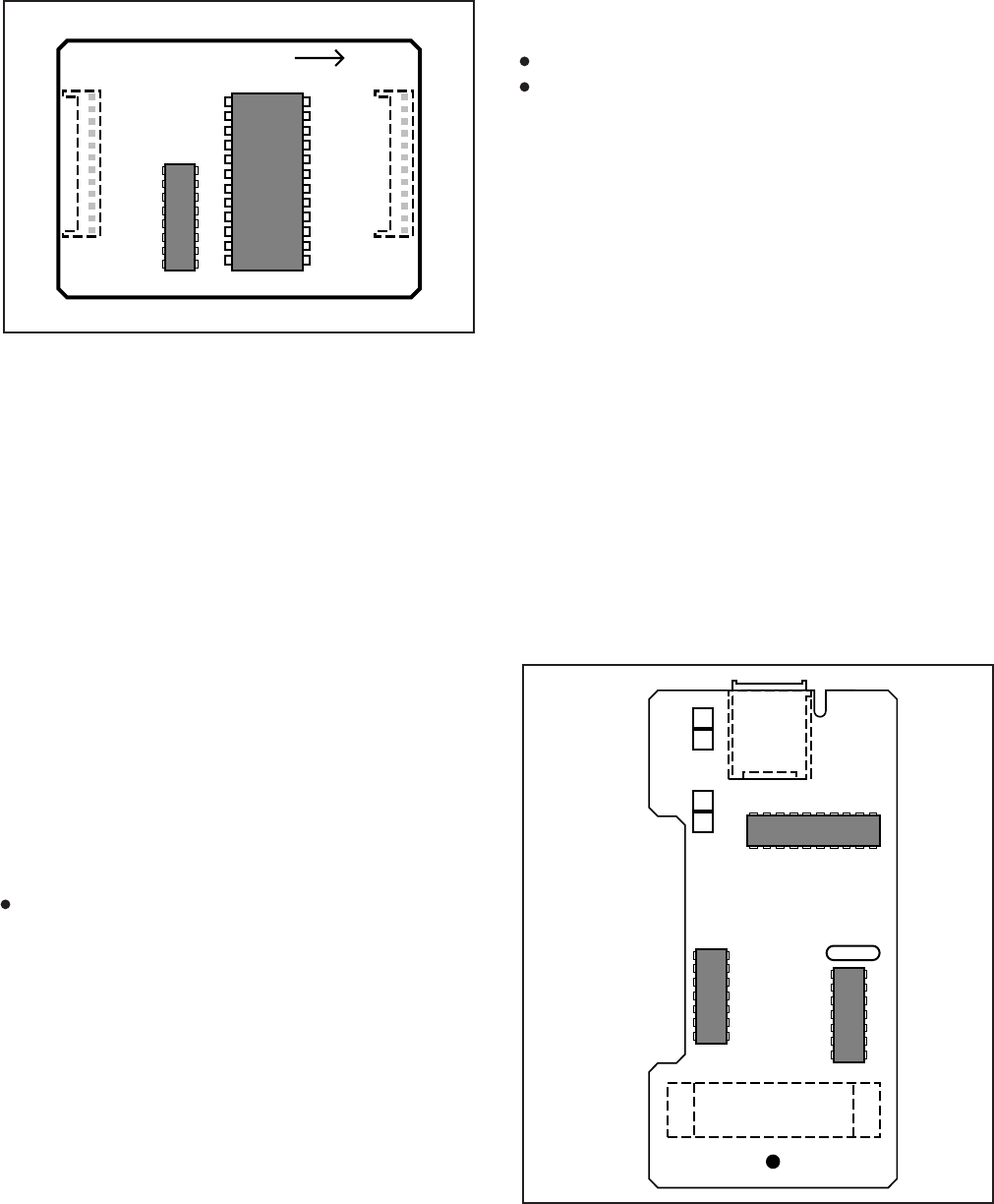
8B
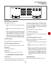
8A
1B
1A
QSMU1A V.1
J1
FIGURE 4-12
QCNU INTERFACE CONNECTORS