


INSTALLATION-DK16 KSU & PCB
SECTION 100-816-205
MARCH 1993
5-12
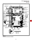
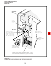
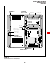
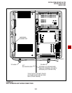
AC DC
DC POWER
–24V CIRCUIT
BREAKER
(RIGHT SIDE)
AC POWER CABLE
MOUNTING HOLE
AND SCREW
MOUNTING
SCREWS (6)
DC OUT (P9) CONNECTOR
(KPSU16 VOLTAGE TEST POINTS)
BATT
±
KRCU
PULL
LOCK
PUSH
UNLOCK
DC CABLE
RESERVE BATTERY
CONNECTOR
DC POWER
SWITCH
FG1 GREEN/YELLOW WIRE RUN
UNDERNEATH POWER SUPPLY
BEHIND STAND-OFFS
(FG) GREEN/YELLOW
WIRE WITH RING
TERMINAL THAT IS
FASTENED TO
POWER SUPPLY
FG SCREW
FG SCREW
(LEFT SIDE)
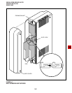
KPSU16A
POWER SUPPLY
GREEN/YELLOW WIRE
(RIGHT-HAND SIDE)
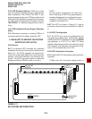
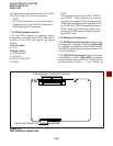
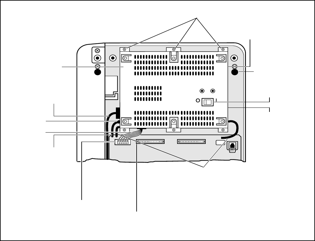
FIGURE 5-10
POWER SUPPLY (KPSU16)
4) Plug the DC cable into the DC OUT connector.
Green/yellow wire is on right-hand side (Figure
5-10).
5) Fasten FG green/yellow wire ring terminal and
building ground wire to the left side of the
power supply with the FG screw.
6) Re-install K4RCU PCB (if required).
7) Plug the AC power cable into an outlet and
turn ON the power supply switch.
8) Refer to Paragraph 2.10 to confirm that the
power supply is working properly.
9) Plug reserve battery cable into BATT connec-
tor of power supply (Figure 5-10).