


8-2
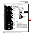
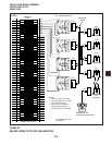
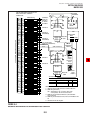
INSTALLATION-WIRING DIAGRAMS
SECTION 100-816-208
MARCH 1993
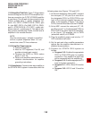
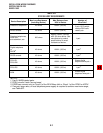
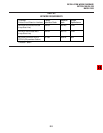
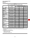
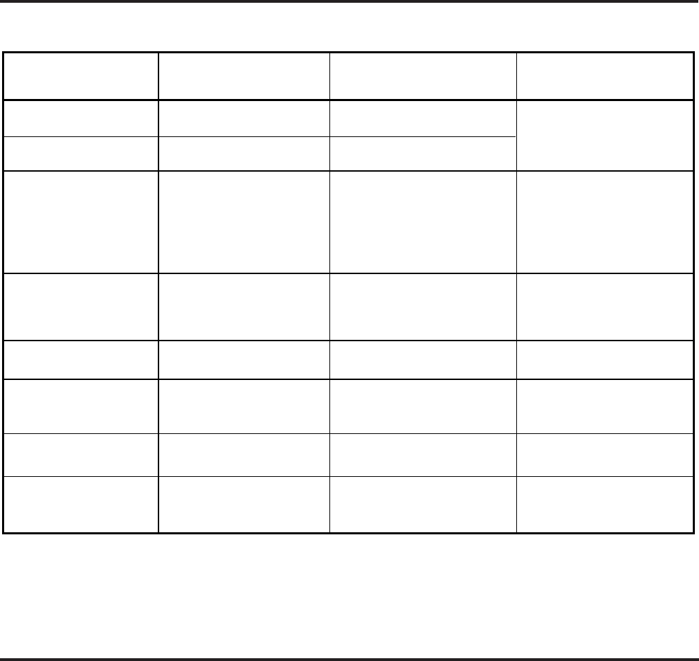
TABLE 8-B
STATION LOOP REQUIREMENTS
NOTES:
1. Use 24 AWG twisted pairs.
2. PESU circuits 3 and 4 are not used.
3. DDCB can connect only to Circuit 5 of the DK16 Base Unit or Circuit 1 of the PDKU or KCDU.
4. Two-pair, larger wire, or local telephone power supply is required to achieve maximum range,
see Table 8-D.
Device Description
Max Loop Resistance
(Including Device)
Max Distance from
KSU to Device
Number of
Wire Pairs
Standard telephones,
voice mail,
auto attendant, etc.
Electronic
4
telephone
HDSS console
Digital telephone
or
DDCB
3
DDSS console
PDIU-DI
PDIU-DI2
PDIU-DS
40 ohms
20 ohms
300 ohms
40 ohms
40 ohms
40 ohms
40 ohms
1000 ft. (303 m)
500 ft. (152 m)
1000 ft. (303 m)
1000 ft. (303 m)
1000 ft. (303 m)
1000 ft. (303 m)
2-pair. EKTs which
receive OCA calls
need 3-pair.
1-pair
1-pair
Shares digital
telephone wire-pair.
4
4
4
1-pair
4
1-pair
1
Approx. 3000 ft. (909 m)
with 150 ohm device. See
manufacturer's product
specifications for exact
resistance of device.
ADM
40 ohms 1000 ft. (303 m)
Shares digital
telephone wire-pair.
4