


5-22
INSTALLATION-DK 16 KSU & PCB
SECTION 100-816-205
MARCH 1993
four electronic telephone interface circuits (5 ~ 8)
identical to PEKU circuits for connecting electronic
telephones, BGM or an external amplifier. The
PESU provides a ring generator for circuits 1 and 2
(with a ring voltage of either 190V P-P or 130V P-
P), and it must be installed in the Expansion Unit.
The PESU does not support an HDSS console
connection.
The PESU provides connectors to mount the
EOCU for OCA to electronic telephones.
NOTE:
A KSU must be installed in the Base Unit for
the system to recognize Dual-Tone Multi-
Frequency (DTMF) tones sent from standard
telephones or other two-wire devices that are
connected to the PESU.
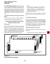
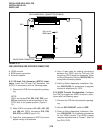
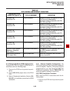
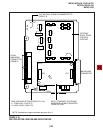
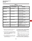
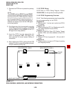
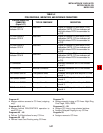
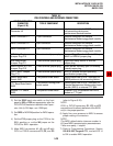
10.02 The PESU controls and interface connec-
tors are shown in Figure 5-16 and described in
Table 5-D.
10.10 PESU Hardware Options
10.11 The PESU supports the following hardware
options:
Internal option: Off-hook Call Announce
(EOCU).
NOTE:
Refer to Section 100-816-206 and Section
100-816-207 for installation of external op-
tions.
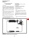
10.12 Off-hook Call Announce (EOCU) Installa-
tion. Install the Off-hook Call Announce in accor-
dance with the following steps:
1) Remove the PCB from its protective packag-
ing.
NOTE:
PESU connectors P10, P20, P40, P50, and
P60 are positioned to allow installation of the
EOCU only in the proper position (refer to
Figure 5-16).
2) Mate the EOCU connectors J10, J20, J40,
J50, and J60 with the PESU connectors P10,
P20, P40, P50, and P60 (refer to Figure 5-16).
potentially hazardous ring voltage. Do not
remove this shield.
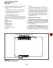
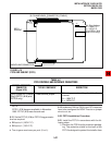
2) Ensure that the PSTU subunit (SSTU) is se-
curely attached to the PSTU (refer to Figure 5-
15).
NOTE:
W1, the ring generator level option, should be
set in the H position (factory) for initial instal-
lation.
3) Insert the PSTU into the appropriate slot (refer
to Paragraph 5.22), and apply firm, even pres-
sure to ensure proper mating of connectors.
9.30 PSTU Wiring
9.31 Refer to PSTU Wiring Diagram, Section 100-
816-208, for wiring/interconnecting details.
9.32 The PSTU is registered for use with OL13A
type lines for off-premises stations.
9.40 PSTU Programming Overview
9.41 The following parameters may be specified,
through programming, for the PSTU:
Program 03
Specify code 31 for all slots that have PSTUs
installed.
Program 31
Used to configure all PSTU ports connected to
voice mail (Section 100-816-207 for more de-
tails).
Program 10-2
Used to set standard telephone ringing option.
Also used for BGM connection.
Program 19
Used for BGM connection also.
10 STANDARD/ELECTRONIC TELE-
PHONE INTERFACE UNIT (PESU)
10.00 General
10.01 The Standard/Electronic Telephone Inter-
face Unit (PESU) provides two standard telephone
interface circuits (1 and 2) identical to PSTU circuits
for connection between standard telephones, or
two-wire devices, and the system. It also provides