


INSTALLATION-STATION APPARATUS
SECTION 100-816-206
MARCH 1993
6-12
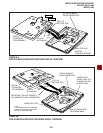
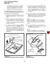
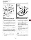
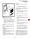
3) Position the HVSU/HVSI subassembly on the
standoffs inside the base, and secure with the
two screws provided (Figure 6-14).
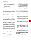
4) Connect the HVSU/HVSI subassembly wire
plug to the P2 connector on the electronic
telephone PCB (Figure 6-13).
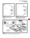
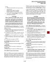
5) Reinstall the electronic telephone base, and
secure it with its four captive screws.
4.20 Loud Ringing Bell/Headset Upgrade
(HHEU)
4.21 The Loud Ringing Bell/Headset upgrade
(HHEU) enables an external speaker (HESB) and/
or a headset to be connected to the electronic
telephone. The HESB serves as a Loud Ringing
Bell when connected to a telephone.
NOTES:
1. There are two types of HHEU: the HHEU1
(which has four versions, V.1 ~ V.4) and
the HHEU2.
2. Only electronic telephones equipped with
an HHEU2 can be wall mounted. The
HHEU2 is identical to the V.4 HHEU1,
except that the HHEU2 has longer wires
to accommodate wall mounting.
3. A Toshiba HESC-65 or HESC-65A cable
is required to connect the HHEU in an
electronic telephone to the HESB. Refer
to Section 100-816-207 for HESB instal-
lation procedures.
4. All HHEU versions and types, except for
V.1 HHEU1, are compatible with the Off-
hook Call Announce upgrades (HVSU2
and HVSU/HVSI).
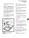
4.22 HHEU Upgrade Installation. Install the HHEU
upgrade in accordance with the following steps:
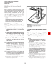
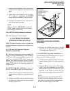
1) Loosen the four captive screws securing the
telephone base (Figure 6-1), and remove the
base.
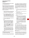
2) Using a screwdriver or other suitable tool,
remove the plastic tab located on the back of
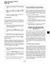
R-UP (6510-H,
6510-S, 6520-S)
TO HHEU
CONNECTOR
P1
TO HVSU
CONNECTOR, P2
ROOM NOISE
BEEP
STRAP
HI
CARBON STRAPS
W201
W202
CARBON
HHEU STRAP
W203
RED
WIRE
RED
RED
R-UP
(6520-SD)
P2
P1
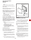
FIGURE 6-13
ELECTRONIC TELEPHONE PCB CONNECTIONS
FIGURE 6-14
HVSI/HVSU INSTALLATION FOR ELECTRONIC
TELEPHONES
TO P2 HVSU
CONNECTOR
ON MAIN PCB
INSIDE
TELEPHONE
HSVI
P5
HVSU