


INSTALLATION-DK8 KSU & PCB
SECTION 100-816-204
MARCH 1993
4-11
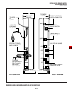
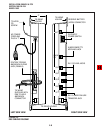
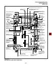
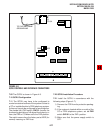
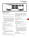
FIGURE 4-8
QCDU CONTROLS AND INTERFACE CONNECTORS
7.02 The QCDU is shown in Figure 4-8.
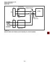
7.10 QCDU Configuration
7.11 The QCDU may have to be configured to
control excessive loudness if the system is close to
a CO or installed behind a PBX telephone system.
It does not have to be configured for anything else.
The decibel (db) PAD switch, SW101 controls the
loudness by providing a 3 db signal level drop to, or
from, the PBX or CO when set to the PAD position.
The switch comes from the factory set at NOR (for
normal) meaning no PAD loss.
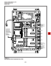
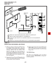
7.20 QCDU Installation Procedure
7.21 Install the QCDU in accordance with the
following steps (Figure 4-7):
1) Remove the PCB from its protective packag-
ing.
2) If the system is located within one mile of the
CO or PBX telephone system, set db PAD
switch SW101 to the PAD position.
3) Make sure that the power supply switch is
OFF.
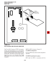
FG
J2
CO 3/4
PAD NOR
J1
TO SYSTEM FRAME
GROUND BAR