


INSTALLATION-DK16 KSU & PCB
SECTION 100-816-205
MARCH 1993
5-4
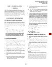
4) Secure screws approximately two thirds of the
way into the top two holes on the mounting
surface.
5) Hang the unit from the top two screws and
then secure the screws completely into the
mounting surface.
6) Finish securing the unit to the mounting sur-
face by completley screwing the bottom two
screws into the wall.
7) Ground system according to Chapter 2, para-
graph 4.
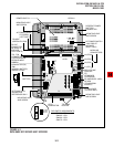
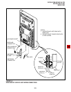
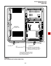
8) Connect applicable wiring (modular CO line
cords, 25-pair amphenol connector cable, etc.)
to the Base Key Service Unit and then fasten
wiring to the unit with the tie wrap that comes
with the base unit (Figure 5-4). Remove
amphenol connector clamp from plastic bag
that comes with the Base Unit. Fasten the
clamp to hold the amphenol connector.
9) Connect Reserve batteries (per Paragraph
2.40) and plug battery cable into BATT con-
nector of the KPSU16 power supply (Figure 5-
3 and 5-4).
10) Set the KCOU PAD switches (SW400-SW475)
to the appropriate position (Figure 5-3). The
factory setting is NORMAL. If CO lines are
connected to a PBX or are in close proximity
to the central office the PAD position may be
required.
11) If the Expansion Key Service Unit is going to
be installed, refer now to Paragraph 2.30. If
not, proceed to Step 12.
12) Plug the AC power cable into an outlet and
then turn ON the power supply switch.
13) Reinstall the front and side covers onto the
Base Key Service Unit.
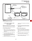
2.30 Mounting the Expansion Key Service
Unit
1) Make sure the side cover is removed from the
Base Key Service Unit. Turn Base Key Ser-
vice Unit DC power switch off.
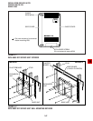
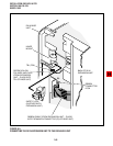
2) Set the Expansion Key Service Unit on the
Base Key Service Unit's hinge mounts, mak-
ing sure that the Expansion Unit sets properly
in place (Figure 5-5).
3) Remove safety lock from plastic bag which
comes with the Expansion Unit. Install safety
lock to the Base Unit as shown in Figure 5-5.
4) Pull out on the safety lock until it can no longer
be moved, securing the Expansion Key Ser-
vice Unit to the Base Key Service Unit (Figure
5-5). Do not detach the lock from the Base Key
Service Unit.
5) Connect the Expansion Key Service Unit Rib-
bon Cable to the connector on the Base Key
Service Unit (Figure 5-5). Close ribbon cable
connector lock on Base Unit.
6) Connect Expansion Unit green/yellow ground
wire plug (FG2) to TB1 of the Base Unit. (Make
sure the plug locks on TB1.) See Figure 5-3
and 5-4.
7) Making sure that the Expansion Key Service
Unit is flush against the mounting surface,
mark the location of the Expansion Unit mount-
ing screw hole (Figure 5-6).
8) Swing the Expansion Key Service Unit away
from the mounting surface, and drill a hole at
the mark made in Step 7.
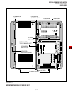
9) Install applicable printed circuit boards (PCBs)
(see Chapter 5, Section II)—after PCBs are
installed, slide the slot lock to the lock position
(Figure 5-7).
10) Swing the Expansion Key Service Unit back to
the mounting surface and secure it to the
surface with a screw.
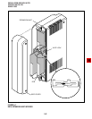
11) Connect applicable wiring (modular CO line
cords, 25-pair amphenol connector, etc.) to
the PCBs (Figure 5-8).
12) Fasten the wiring with tie wraps (supplied) to
the bottom of the Expansion and Base Key
Service Units (Figure 5-8).