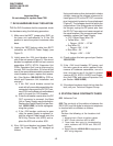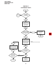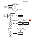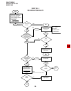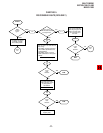
FAULT FINDING
SECTION 100-816-500
MARCH 1993
-6-
NOTES:
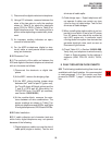
1. This is the maximum allowable reading for all Digital and Electronic telephone cable runs except if connecting an HDSS
console to Circuits 7 and 8 of a PEKU—then the maximum cable restriction is 20 ohms, not 40 ohms.
2. The green-red, black-yellow and white-blue measurements should be within 10% of each other.
3. Nominal voltage—within the limits of
±
26.3 ~
±
27.8 VDC while under AC power, polarity depending on voltmeter lead
placements.
Pair
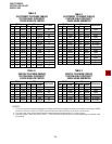
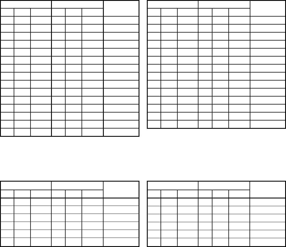
TABLE C
(ELECTRONIC TELEPHONE CABLES)
STATION CABLE CONTINUITY
CHECK USING OHMMETER
1
1
1
1
1
2
3
3
3
3
3
3
3
3
Wire
T
R
T
R
T
T
T
T
R
T
R
T
R
T
Color
Green
Red
Green
Red
Green
Black
White
White
Blue
White
Blue
White
Blue
White
FROM
Pair
2
2
2
2
1
2
3
1
1
1
1
2
2
2
Wire
T
T
R
R
R
R
R
R
R
T
T
T
T
R
Color
Black
Black
Yellow
Yellow
Red
Yellow
Blue
Red
Red
Green
Green
Black
Black
Yellow
TO
Resistance
open
open
open
open
40 ohms
40 ohms
40 ohms
open
open
open
open
open
open
open
1
1
1
Pair
TABLE E
(DIGITAL TELEPHONE CABLES)
STATION CABLE CONTINUITY
CHECK USING OHMMETER
1
1
1
1
1
2
Wire
T
R
T
R
T
T
Color
Green
Red
Green
Red
Green
Black
FROM
Pair
2
2
2
2
1
2
Wire
T
T
R
R
R
R
Color
Black
Black
Yellow
Yellow
Red
Yellow
TO
Resistance
open
open
open
open
40 ohms
40 ohms
1
1
Pair
TABLE D
(DIGITAL TELEPHONE CABLES)
STATION CABLE CONTINUITY
CHECK USING VOLTMETER
1
1
1
1
1
2
Wire
T
R
T
R
T
T
Color
Green
Red
Green
Red
Green
Black
FROM
Pair
2
2
2
2
1
2
Wire
T
T
R
R
R
R
Color
Black
Black
Yellow
Yellow
Red
Yellow
TO
VOLTAGE
0
24
24
0
24
24
3
3
3
3
Pair
TABLE B
(ELECTRONIC TELEPHONE CABLES)
STATION CABLE CONTINUITY
CHECK USING VOLTMETER
1
1
1
1
1
2
3
3
3
3
3
3
3
3
3
Wire
T
R
T
R
T
T
T
T
R
T
R
T
R
T
R
Color
Green
Red
Green
Red
Green
Black
White
White
Blue
White
Blue
White
Blue
White
Blue
FROM
Pair
2
2
2
2
1
2
3
1
1
1
1
2
2
2
2
Wire
T
T
R
R
R
R
R
R
R
T
T
T
T
R
R
Color
Black
Black
Yellow
Yellow
Red
Yellow
Blue
Red
Red
Green
Green
Black
Black
Yellow
Yellow
TO
VOLTAGE
3
24
24
24
24
0
0
0
0
0
0
0
0
0
0
0
3
3
3
3


