


5-32
INSTALLATION-DK 16 KSU & PCB
SECTION 100-816-205
MARCH 1993
a CO or installed behind a PBX telephone system.
It does not have to be configured for anything else.
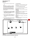
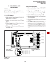
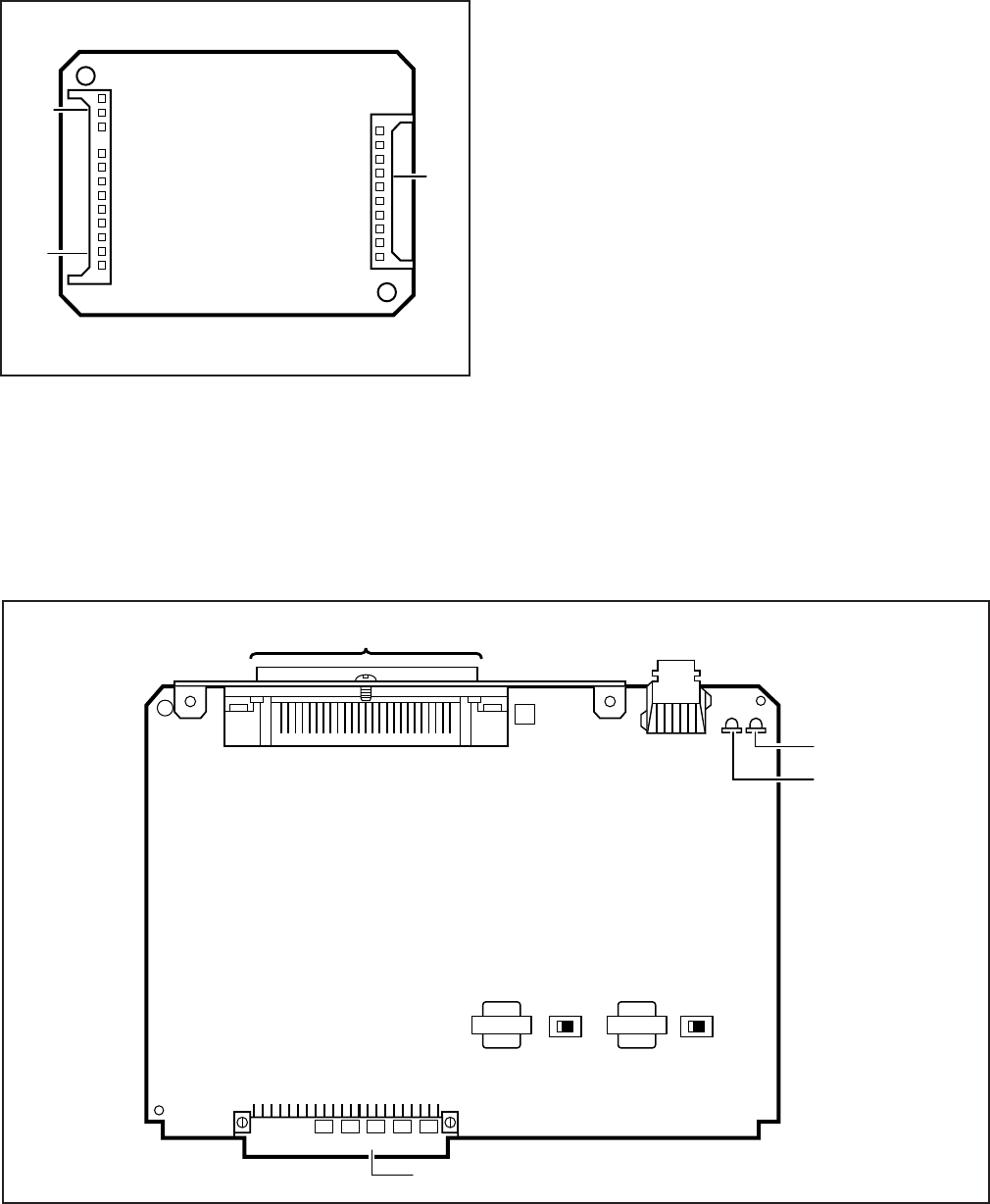
The decibel (db) PAD switches, SW501 (CO1) and
SW601 (CO2), control the loudness by providing a
3 db signal level drop to, or from, the PBX or CO
when set to the PAD position. The switch comes
from the factory set at NOR (for normal) meaning
no PAD loss.
13.20 KCDU Installation Procedure
13.21 Install the KCDU in accordance with the
following steps:
1) Remove the PCB from its protective packag-
ing.
2) If the system is located within one mile of the
CO or PBX telephone system, set db PAD
switches SW501 and SW601 to the PAD
position.
3) Insert the KCDU into the appropriate slot (04
first, 05 second) in the Expansion Unit, and
apply firm, even pressure to ensure proper
mating of the connectors.
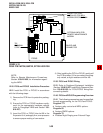
FIGURE 5-20
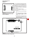
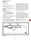
REMOTE MAINTENANCE MODEM UNIT (IMDU)
IINTERFACE CONNECTORS
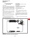
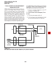
FIGURE 5-21
KCDU INDICATORS, OPTIONS, AND CONNECTORS
J3
J2
J1
BACKPLANE CONNECTOR
25-PAIR AMPHENOL CONNECTOR (FEMALE)
CO2
CO1
SW501
(CO1)
SW601
(CO2)
PAD NORPAD NOR
J7