


5-21
INSTALLATION-DK 16 KSU & PCB
SECTION 100-816-205
MARCH 1993
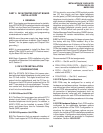
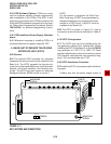
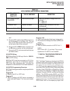
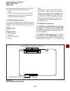
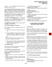
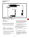
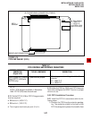
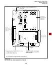
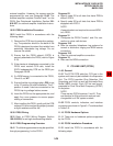
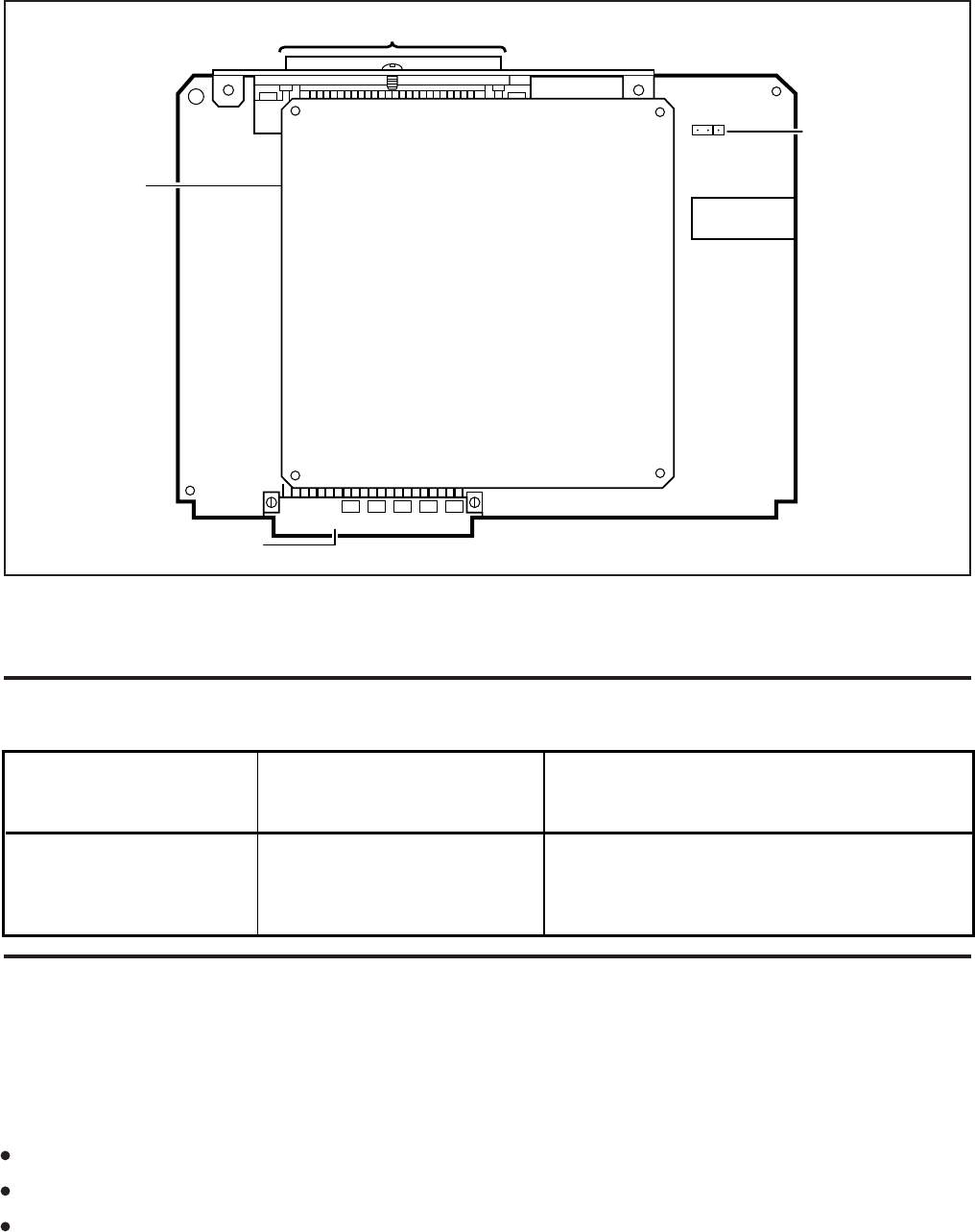
FIGURE 5-15
PSTU AND SUBUNIT (SSTU)
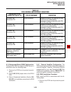
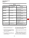
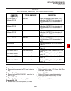
TABLE 5-C
PSTU CONTROLS AND INTERFACE CONNECTORS
CONTROL/INDICATOR/
CONNECTOR
(Figure 5-15)
TYPE OF COMPONENT DESCRIPTION
Ring Voltage W1 Jumper
Plug (PSTU1 ( ) and
PSTU2 only)
Three-terminal jumper
Sets ring generator voltage level for all
circuits.
H = 190V P-P
L = 130V P-P
V.4
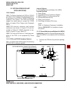
BACKPLANE CONNECTOR
50-PIN AMPHENOL CONNECTOR (FEMALE)
SSTU
SUBUNIT
W1
HL
W1 Ring Voltage
H = 190V P-P
L = 130V P-P
(For PSTU1 (V.4)
and PSTU2 only)
9.13 Unlike the PEKU or PESU, the PSTU does not
have to be configured for BGM: There is no jumper
wire to cut, etc.
9.20 PSTU Installation Procedure
9.21 Install the PSTU in accordance with the fol-
lowing steps:
1) Remove the PCB from its protective packag-
ing. The protective shield on the back of the
PSTU is designed to protect the installer from
NOTE:
PSTU1 (V.4) became available in November
1989. PSTU1(V.3) was discontinued.
9.12 Set the PSTU1 (V.4) or PSTU2 ring generator
level as required:
W1 set to H (190V P-P).
W1 set to L (130V P-P).
Two ringers maximum per port (H or L).