5-20
INSTALLATION-DK 16 KSU & PCB
SECTION 100-816-205
MARCH 1993
Specify code 24 to indicate a PEKU configured
for OCA and an HDSS console.
Program 10-2
Used for BGM connection.
Program 10-3
Used for external amplifier connection.
Program 19
Also used for BGM connection.
Programs 28 and 29
Used for HDSS assignments.
9 STANDARD TELEPHONE
INTERFACE UNIT (PSTU)
9.00 General
9.01 The Standard Telephone Interface Unit
(PSTU) provides an interface between standard
telephones or two-wire devices and the system,
and it must be installed in the Expansion Unit. The
PSTU PCB adds eight standard telephone lines to
the system. The PSTU can also support a Back-
ground Music (BGM) source.
NOTE:
For the system to recognize the Dual-Tone
Multi-Frequency (DTMF) tones generated by
a standard telephone (or any other device
connected to a PSTU port), a DTMF Receiver
Unit (K4RCU) must be installed in the Base
Unit.
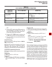
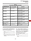
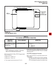
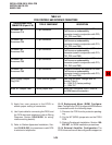
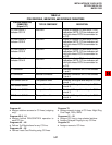
9.02 PSTU controls are shown in Figure 5-15 and
described in Table 5-C.
9.10 PSTU (1 and 2) Hardware Options
9.11 There are two PSTU versions (1 and 2): They
are identical except for the ring generator. The ring
generator on the original version (V.3) of PSTU1 is
fixed at a 190V P-P level, while the ring generator
on PSTU1 (V.4) and PSTU2 can be set for 130V P-
P or 190V P-P. The W1 jumper plug is used to set
the voltage level. Most standard telephones and
two-wire devices require the 190V P-P level; how-
ever, some devices may experience ring-trip with
190V P-P and they require the 130V P-P level.
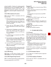
2) Ensure the PEKU has been configured for the
appropriate hardware options (refer to Para-
graph 8.10).
3) Insert the PEKU into the appropriate slot (refer
to Paragraph 5.22), and apply firm, even pres-
sure to ensure proper mating of connectors.
4) After installing the PEKU, gently pull the PCB
outward. If the connectors are properly mated,
a slight resistance will be felt.
8.30 PEKU Wiring
8.31 Refer to PEKU Wiring Diagrams, Section
100-816-208, for wiring/interconnecting details.
8.40 PEKU Programming Overview
8.41 The following parameters may be specified,
through programming, for the PEKU:
Program 03
Specify code 21 to indicate a station line PEKU.
Specify code 22 to indicate a PEKU configured
for OCA.
Specify code 23 to indicate a PEKU configured
for an HDSS console.
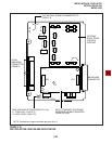
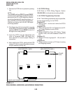
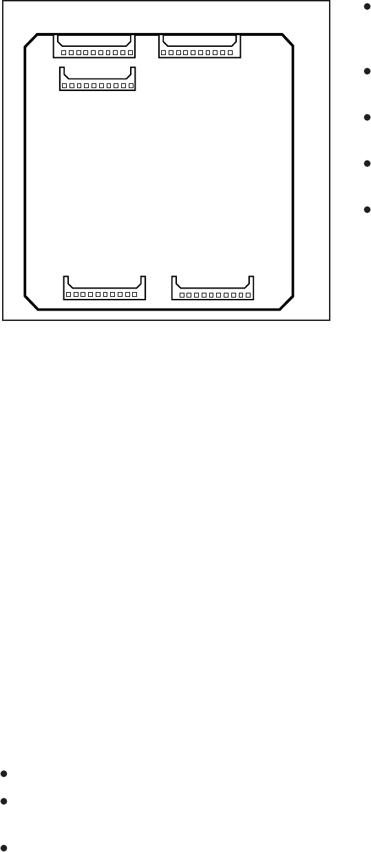
J60
J50
J40
J20 J10
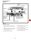
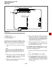
FIGURE 5-14
OFF-HOOK CALL ANNOUNCE UNIT (EOCU)
INTERFACE CONNECTORS


