


5-17
INSTALLATION-DK 16 KSU & PCB
SECTION 100-816-205
MARCH 1993
for a DDSS console and OCA.
Programs 20, 21, and 22
Use to configure PDIU-DIs/PDIU-DI2s and PDIU-
DSs.
Programs 28 and 29
Use for DDSS assignments.
Program 30
Adjusts initial off-hook volume level for digital
telephone handsets.
Program 92-5
Initializes initial ringing, speaker, and muted ring
volume levels of digital telephones.
Programs 77-1, 77-2, and 79
Used for DDCB and door phone assignments
8 ELECTRONIC TELEPHONE
INTERFACE UNIT (PEKU)
8.00 General
8.01 The Electronic Telephone Interface Unit
(PEKU) provides eight ports for electronic tele-
phones and it must be installed in the Expansion
Unit. It is recommended that the current 6500-
series be used, because this series consumes the
least amount of power.
8.02 The PEKU can be configured to receive Off-
hook Call Announce (OCA) by installing an Off-
hook Call Announce Unit (EOCU). It can also be
configured to support an HDSS console and an
external Background Music (BGM) source connec-
tor. An external amplifier for two-CO line confer-
ence calls can also be connected to Circuits 6 and
7 of the PEKU. The HDSS console, the external
amplifier, and the BGM source, are wired directly to
the PEKU and require no additional hardware, but
do require specific ports/circuits. Electronic tele-
phones also wire directly to the PEKU, and they can
be connected to any PEKU circuit.
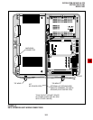
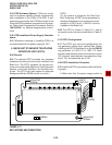
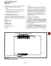
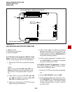
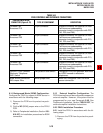
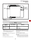
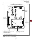
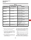
8.03 PEKU controls and interface connectors are
shown in Figure 5-13 and described in Table 5-B.
8.10 PEKU Hardware Options
8.11 The PEKU supports the following hardware
options:
Internal Options
Off-hook Call Announce Unit (EOCU)
External Options
Circuits 1 ~ 8 on a PDKU2; the circuit must be
dedicated to the PDIU-DS.
7.15 PDIU-DI/PDIU-DI2 Configuration. Refer to
Station Apparatus Installation, Section 100-816-
206, and Peripherals Installation, Chapter 7, for
installation procedures for the PDIU-DI/PDIU-DI2.
PDIU-DIs/PDIU-DI2s can be equipped with any
digital telephone connected to PDKU Circuits 1 ~ 7
with PDKU1 or Circuits 1 ~ 8 with PDKU2.
7.16 DDCB Configuration. Refer to Peripherals
Installation, Section 100-816-207, for installation
procedures for the DDCB. The DDCB must be
connected to the Circuit 8 on the PDKU.
7.17 ADM Configuration. Refer to Section 100-
816-206, Paragraph 7.00.
7.20 PDKU Installation Procedure
7.21 Install the PDKU in accordance with the fol-
lowing steps:
1) Remove the PCB from its protective packag-
ing.
2) Insert the PDKU into the appropriate slot (see
Paragraph 5.22, and apply firm, even pres-
sure to ensure proper mating of connectors.
NOTE:
Ensure the PDKU's component side is facing
right when installing it in the KSU.
4) After installing the PDKU, gently pull the PCB
outward. If the connectors are properly mated,
a slight resistance will be felt.
7.30 PDKU Wiring
7.31 Refer to PDKU Wiring Diagrams, Chapter 8,
for wiring/interconnecting details.
7.40 PDKU Programming Overview
7.41 The following parameters may be specified,
through programming, for the PDKU:
Program 03
Specify code 61 if no options are installed on a
PDKU.
Specify code 62 to indicate a PDKU that will
support stations that must receive Off-hook Call
Announce (OCA).
• Specify code 64 to indicate a PDKU configured