


5-16
INSTALLATION-DK 16 KSU & PCB
SECTION 100-816-205
MARCH 1993
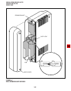
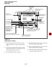
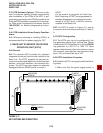
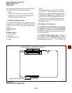
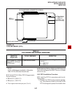
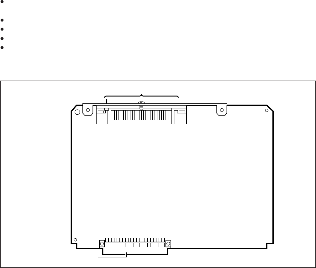
FIGURE 5-12
PDKU INTERFACE CONNECTION
BACKPLANE CONNECTOR
50-PIN AMPHENOL CONNECTOR (FEMALE)
NOTE:
There are two versions of the PDKU: PDKU1,
and PDKU2. These versions are identical
except for the number of Data Interface Units
(DIUs) they can support (see Paragraphs 7.14
and 7.15). Also, PDKU2 supports continuous
DTMF tones with 2000-series digital tele-
phones, but PDKU1 does not support continu-
ous DTMF tones.
7.12 Hardware Configuration
7.13 DDSS Console Configuration. Refer to Sta-
tion Apparatus Installation, Section 100-816-206,
for installation procedures for the DDSS console.
The DDSS console requires dedicated use of Cir-
cuit 8 of the PDKU.
7.14 PDIU-DS Configuration. Refer to Peripher-
als Installation, Section 100-816-207, for installa-
tion procedures for the PDIU-DS. A PDIU-DS can
be connected to Circuits 1 ~ 7 on a PDKU1 or
phone the same wire pair and circuit on the PDKU.
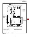
The PDKU (Figure 5-12) has no controls.
NOTE:
The PDIU-DI attaches to 1000-series Digital
Telephones, and the PDIU-DI2 attaches to
2000-series Digital Telephones.
7.10 PDKU Hardware Options
7.11 The PDKU supports the hardware options
noted below. Unlike the other PCBs, there are no
controls on the PDKU that need to be set for
options.
Internal option:
none
External option:
DDSS console
PDIU-DS
PDIU-DI/PDIU-DI2
DDCB