


INSTALLATION-PERIPHERALS
SECTION 100-816-207
MARCH 1993
7-32
Program 35: LED 20 should be ON to assign
auto attendant ports the “Busy Station Trans-
fer” option. with this option the auto attendant
will receive ring backtone when calling sta-
tions designated with “Busy Station Ringing”
(Program 35, LED 19 ON). This allows the
auto attendant to transfer calls to busy sta-
tions. Set LED 19 ON for answer position
stations.
Program 36: Set fixed call forward to VM/AA
port per customer requirements.
Program 37: Set the timer for the VM/AA
ports to 22 seconds minimum to allow call
forward no answer to work on VM transferred
calls.
Program 39: Set the Message Waiting Indi-
cation, Fixed Call Forward, Redial, and Speed
Dial Select buttons on the digital and elec-
tronic telephones that will be used to commu-
nicate with the VM/AA device.
NOTE:
Message Waiting (Msg) and Redial buttons
are fixed buttons on digital telephones and it is
not necessary to assign them in Program 39.
Speed Dial is initialized as Button 20 on
Digital telephones.
Programs 81 ~ 89: Verify that the ringing
assignments to the VM/AA devices are set
per customer requirements.
Programs 16, 40, 41, 45 ~ 48 and 50 ~ 56:
Verify that outgoing CO line access is al-
lowed on VM ports to allow the VM/AA beeper
notification feature to operate.
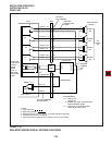
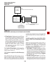
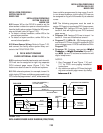
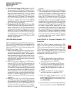
7.25 Voice Mail System Installation. Install the
voice mail messaging system in accordance with
the following steps (See Figure 7-22):
1) Ensure that the QSTU, KSTU, PSTU, or PESU
PCB is installed in the system per Section
100-816-204 (DK8) or Section 100-816-205
(DK16).
2) Connect the voice mail messaging system to
the selected QSTU, KSTU, PSTU, or PESU
standard telephone ports (refer to Wiring Dia-
grams, Section 100-816-208, for QSTU, PSTU,
KSTU, and PESU wiring/interconnecting de-
tails).
3) Program the system for the required voice
mail messaging features (refer to Paragraphs
7.13 and 7.22).
4) Ensure that the DK8 QRCU or DK16 K4RCU
is installed, and (for DK16) verify that the CTU
code in Program 03 is for KRCU-4 operation
as required (this is not required for DK8 QRCU).
5) Perform additional voice mail messaging sys-
tem programming as applicable (refer to cus-
tomer-supplied installation/programming
manuals).
NOTE:
Some voice mail devices may ring trip when
called; in this case, set the ring voltage jumper
to L (low position) on the QSTU, KSTU, PESU,
or PSTU2 PCB connected to the voice mail
device.
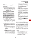
8 DK16 ALARM SENSOR INSTALLATION
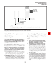
8.00 The PIOU or PIOUS PCB provides a circuit
that can be set to detect a relay open or closed
condition from a facility alarm system. When the
sensor is activated, all electronic and digital tele-
phones will sound an alarm signal. The electronic/
digital telephone alarm signal can be reset by any
electronic or digital telephone with an alarm reset
button (see Program 39).
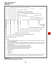
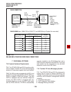
8.01 Alarm Sensor Options. Jumper plug P12 on
the PIOU is used to set the alarm sensor to detect
an open or closed condition from the facility alarm
system. Set P12 as follows (refer to Figure 7-23):
To detect a closed condition, set P12 to the N.O.
position.
To detect an open condition, set P12 to the N.C.
position.