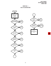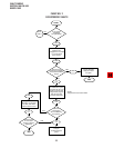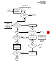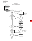
FAULT FINDING
SECTION 100-816-500
MARCH 1993
-4-
Important Note:
Do not attempt to replace Fuse F201
7 DK16 HARDWARE FAULT ISOLATION
7.01 If a DK16 hardware fault is suspected, check
the hardware using the following procedure:
1) Make sure the BATT jumper plug (SW1 on
the base unit motherboard) is in the ON
position to save the system’s customer data
base.
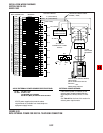
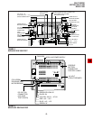
2) Unplug the PBTC battery cable from BATT
connector on KPSU16 Power Supply (see
Figure 2).
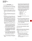
3) Lightly press the -24V circuit breaker to en-
sure it has not opened (Figure 3). If the circuit
breaker has opened and will not rest, remove
assemblies (KSTU, KCOU, Expansion Unit
PCBs, Expansion Unit) one at a time and try
to reset -24V circuit breaker. If it is found lthat
one of the removable assemblies causes the
circuit breaker to open, replace that assem-
bly. (See Section 100-816-205 for PCB re-
moval and Expansion Unit installation and
removal.)
a) If the -24V circuit breaker cannot be
reset with all removable assemblies dis-
connected, disconnect the DC OUT con-
nect (P9) from the Base unit motherboard
and try to reset the -24V breaker.
b) If the circuit breaker resets when the DC
OUT connector is removed, the Base
Unit or Power Supply may be defective.
Replace the Power Supply first (per Sec-
tion 100-816-205) to avoid reprogram-
ming the system.
c) If the -24V breaker continues to open
;after the power Supply is replaced, in-
stall the original Power supply onto the
DK16 Key Service Unit (KSU) and re-
place the KSU with another KSU.
4) If the –24V circuit breaker is not open (Step 3)
check the Power Supply DC voltages as
follows:
Using a voltmeter or other device which checks
voltage, measure the voltages referenced to
frame ground (FG) at the DC OUT connector
pins (test points) located on the motherboard
(Figure 2). The voltages should fall within the
ranges below. If the voltages do not fall within
the ranges, unplug the DC power pins from
the DC OUT connector and measure again at
the same location; if the ranges remain unac-
ceptable, replace the Power Supply.
(FG) Yellow-Green Wire: 0V
Yellow Wire: – 24V
• Range: –26.3V ~ –27.8V
Red Wire: 5V
• Range: 4.5V ~ 5.5V
Blue Wire: –5V
• Range: –4.5V ~ –5.5V
4) Check system third wire ground per Section
100-816-202.
5) If the –24V circuit breaker, DC power, and
third wire ground are within required limits,
remove all hardware assemblies, one at a
time, and test to see if the fault is cleared
(remove KSTU, KCOU, K4RCU and Expan-
sion Unit PCBs and remove Expansion Unit
per Section 100-816-205).
6) If the above hardware check did not clear the
fault, call your Technical Support Group.
8 STATION CABLE CONTINUITY CHECK
8.01 Voltmeter Test
8.02 The continuity of the cable run between the
DK16 KSU and the digital or electronic telephone
is checked with a voltmeter as follows:
NOTE:
Perform the following at the locations indi-
cated:
1. Modular block: Check all stations cables.
2. MDF: Check cable from KSU to MDF.
3. These tests also apply for troubleshooting
cable problems with DDCB and PDIU-DS
devices.
4. Refer to
Section 100-816-208
for appropriate
MDF wiring diagrams.


