INSTALLATION-STATION APPARATUS
SECTION 100-816-206
MARCH 1993
6-14
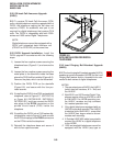
1) Loosen the four captive screws securing the
telephone base (Figure 6-1), and remove the
base.
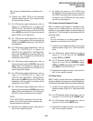
2) Refer to Figure 6-13, and locate the CAR-
BON straps, W201 and W202. Cut both
straps.
3) Reinstall the telephone base, and secure it
with its four captive screws.
4.40 Beep Strap
4.41 A "beep" sounds whenever a dialpad button
or feature button is pressed on an electronic
telephone. This beep can be eliminated with the
following procedure:
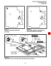
1) Remove the four captive screws securing the
telephone base to the telephone (Figure 6-1),
and remove the base.
2) Locate and cut the BEEP strap on the tele-
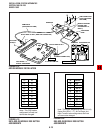
phone printed circuit board (PCB) (Figure 6-
13).
3) Reinstall the electronic telephone base, and
secure in place using the four captive screws.
4.50 Microphone/Speaker Threshold (Speak-
erphones only)
4.51 High ambient noise levels may cause the
speaker on the electronic telephone speakerphone
models (the EKT6510-S, the EKT6520-S, and the
EKT6520-SD) to cut off frequently. To make these
telephones less sensitive to noise and to prevent
the cut-off, follow the steps below:
1) Remove the four captive screws securing the
base to the telephone, and remove the base
(Figure 6-1).
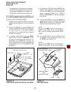
2) Locate the ROOM NOISE switch on the
printed circuit board (PCB) inside the tele-
phone, and push it carefully to the HI (high)
position (Figure 6-13).
3) Reinstall the telephone base and secure in
place using the four captive screws.
4.60 Handset Receiver Volume-up Strap
(Version 2 6500-series Telephones Only)
4.61 For Version 2 (V.2) 6500-series electronic
telephones only, the handset receiver volume can
be increased six decibels (db) by cutting a strap
inside of the telephone. Cut the strap in accor-
dance with the following steps:
1) Remove the four captive screws securing the
telephone base to the telephone, and remove
the base (Figure 6-1).
2) Locate the R-UP strap on the printed circuit
board (PCB) inside the telephone, and cut it
(Figure 6-13).
3) Reinstall the telephone base, and secure in
place using the four captive screws.
5 DIRECT STATION SELECTION
CONSOLE/SYSTEM CONNECTION
(DK16 Only)
5.01 STRATA DK16 systems configured with just
a Base Unit can support one Direct Station Selec-
tion Console, and systems with the optional Ex-
pansion Unit can support two consoles. There are
two types of consoles: the DDSS console and the
HDSS console. The DDSS console can be con-
nected to designated digital telephone circuits,
and the HDSS console can only be connected to
designated PEKU circuits. This section provides
instructions on how to install both types of con-
soles.
5.10 DDSS Console Connections
5.11 The DDSS console, which can operate with a
digital or electronic telephone (preferably an LCD
model), can connect only to Circuit 8 of the Base
Unit digital telephone circuit set or Circuit 8 of the
PDKU. Standard twisted single-pair or two-pair
jacketed telephone cable (maximum 1000 feet,
303 meters) is used for the connection. To accom-
modate the DDSS console connection, the instru-
ment end of the cable should be terminated in a
modular station connector block (RJ-11). Refer to
Wiring Diagrams, Section 100-816-208, for wiring/
interconnecting details, including cable length limi-
tations (see Table 8-D).


