


FAULT FINDING
SECTION 100-816-500
MARCH 1993
-5-
1) Disconnect the digital or electronic telephone.
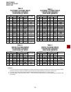
2) Using a DC voltmeter, measure between the
wires of the two pairs to verify the readings
shown in Table B for electronic telephone
ports (PEKU or PESU). Refer to Table D for
digital telephone ports. The reading will be a
plus or minus depending on meter lead place-
ment.
3) An improper reading indicates an open,
crossed or shorted wire.
4) For the MDF-to-telephone (digital or elec-
tronic) cable, a more precise check is made
using an ohmmeter.
8.10 Ohmmeter Test
8.11 The continuity of the cable run between the
KSU and digital or electronic telephone is checked
with an ohmmeter as follows:
1) Disconnect the electronic or digital tele-
phone.
2) At the MDF, remove the bridging clips.
3) At the MDF, place shorting jumper wires
between the T and R of pair #1 (green-red),
the T and R of pair #2 (black-yellow) and the
T and R of OCA pair #3 (blue-white), for
PEKU/PESU only. (For MDF pin numbers,
see Section 100-816-208.)
4) At the modular block, measure the resis-
tance between all wire combinations. The
proper readings are shown in Table C for
electronic telephones and HDSSs, and Table
E for digital telephones, DDSSs and DDCBs.
8.20 Cable Installation
8.21 If cable voltmeter and ohmmeter tests are
within limits, digital telephones may not operate
because of the following:
1) Digital telephone cable runs must be free of
cable splits (single or double). Test for and
eliminate all cable splits.
2) Cable bridge taps – Digital telephones will
not operate if cable runs contain any type
(short or long) of cable bridge. Test for and
eliminate all cable bridges.
3) When installing the station cable, do not run
parallel to and within 3 feet of an AC power
line. AC power lines should be crossed at
right (90°) angles only. In particular, avoid
running station wire pairs near devices that
generate electrical noise, such as neon or
fluorescent light fixtures.
4) Check Table 8-D, in Section 100-816-208.
Verify that your telephone is wired correctly
(2-pair or External power) for the options it
supports (ADM, PDIU-DI, HHEU, DVSU,
etc.).
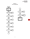
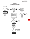
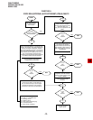
9 FAULT ISOLATION FLOW CHARTS
9.01 The following troubleshooting flow charts are
available to aid in fault isolation. It is recommended
to read paragraph 1~5 of this section and then
proceed to CHART 1, page 7, to begin fault isola-
tion.