


INSTALLATION-PERIPHERALS
SECTION 100-816-207
MARCH 1993
7-41
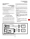
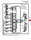
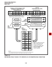
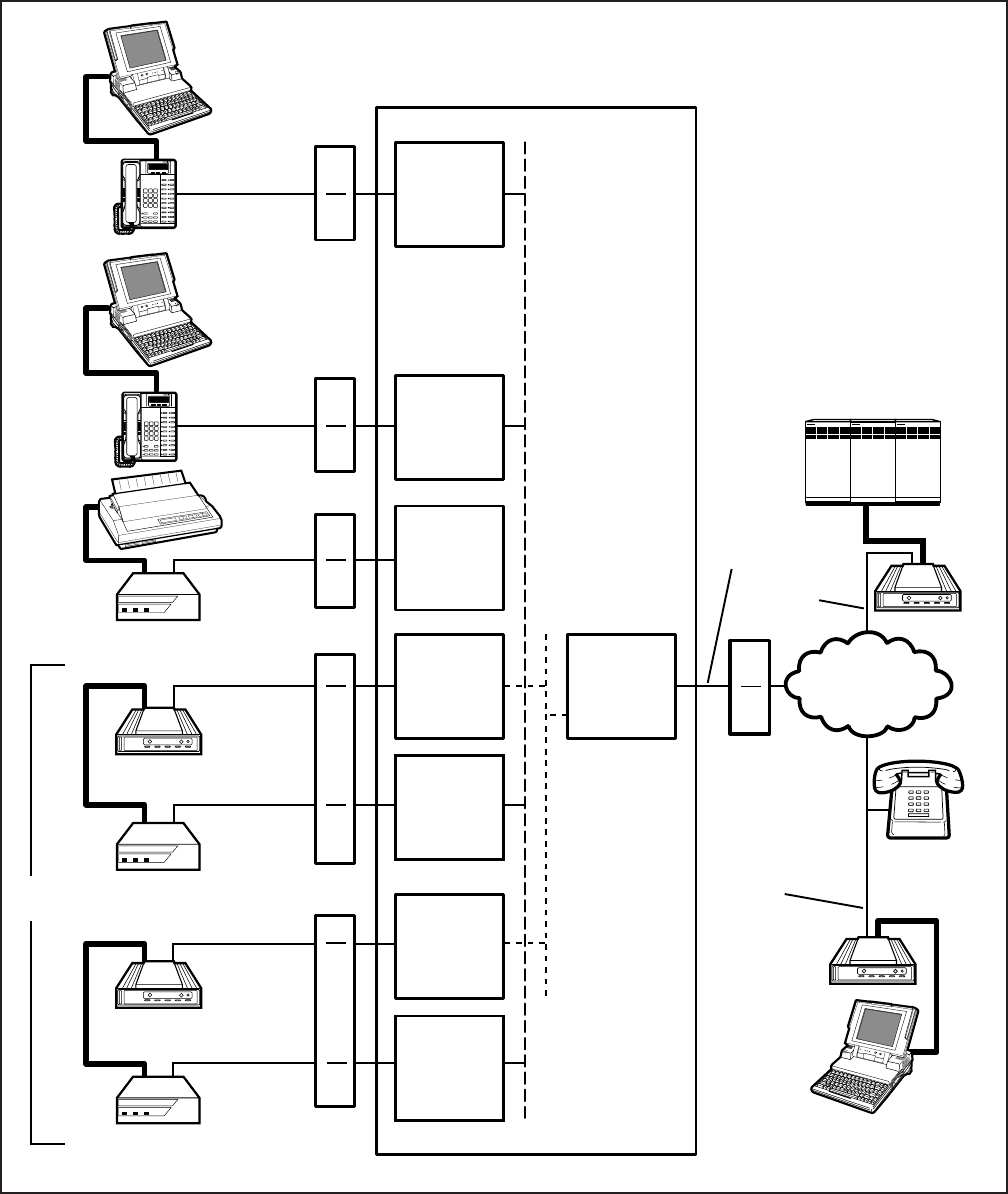
FIGURE 7-24
DK8 OR DK16 DATA INSTALLATION EXAMPLE BLOCK DIAGRAM
DIGITAL
(PORT 05)
QSTU
OR
KSTU
(PORT 08)
DIGITAL
(PORT 03)
DIGITAL
(PORT 00)
DIGITAL
(PORT 01)
TOSHIBA
DIU
POWER READYCONNECT
TOSHIBA
QSTU
OR
KSTU
(PORT 09)
DIGITAL
(PORT 04)
DIU
POWER READYCONNECT
TOSHIBA
DIU
POWER READYCONNECT
TOSHIBA
LAPTOP, PC 1
RS-232
1
DKT/PDIU-DI
(10)
MDF
2
MDF
2
MDF
2
MDF
3
MDF
3
RS-232
1
RS-232
1
RS-232
1
RS-232
1
LAPTOP, PC 2
DKT/PDIU-DI
(11 )
SERIAL
PRINTER
PDIU-DS
(13)
MODEM
(18)
PDIU-DS
(14)
MODEM 1
(19)
PDIU-DS
(15)
MODEM
POOL
MODEM
MDF
CO
LINE 1
PUBLIC
TELEPHONE
NETWORK
TELEPHONE
LINE X
TELEPHONE
LINE Y
RS-232
1
LAPTOP,
PC 3
DIAL-UP
COMPUTER
SERVICE
NOTES:
1. RS-232 cable and connector
information is provided in
Figures 7-25 to 7-32.
2. PDIU-DI/PDIU-DS MDF
station wiring to Digital Ports,
is in Section 100-816-208.
3. Modem MDF station wiring to
QSTU, KSTU, PSTU or PESU
is in Section 100-816-205.
STRATA DK16 KSU
MODEM
RS-232
1
LINE Z
STANDARD
TELEPHONE