


INSTALLATION-SITE REQUIREMENTS
SECTION 100-816-202
MARCH 1993
2-1
1 GENERAL
1.00 This chapter defines the installation site re-
quirements necessary to ensure a proper operat-
ing environment for the STRATA DK8 and DK16.
Also included are grounding requirements.
2 INPUT POWER REQUIREMENTS
2.00 The system requires an input power source
of 117VAC nominal (85VAC ~ 135VAC), 50/60 Hz,
15 amps. The AC outlet is recommended to be
dedicated
and unswitched, with a solid third wire
ground (refer to Paragraph 4). This is to eliminate
interference from branch circuit motor noise or the
like, and to prevent accidental power-off.
2.01 To avoid accidental power turn-off, it is rec-
ommended that an ON/OFF wall switch
not
be
used on this dedicated AC circuit.
2.02 An option Reserve Power Battery and
Charger (HPFB) is available for use with the
STRATA DK8 to serve as a power failure backup.
For the STRATA DK16, a reserve power source
(two customer-supplied 12-volt batteries) may be
connected to the system to serve as a power
failure backup.
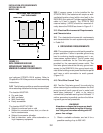
3 SITE CONSIDERATIONS
3.00 Clearance and Location Requirements
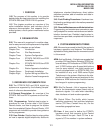
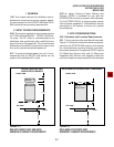
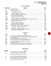
3.01 The key service units must be wall mounted.
Figure 2-1 shows the minimum clearance require-
ments for the STRATA DK8 system, and includes
the recommended mounting location and clear-
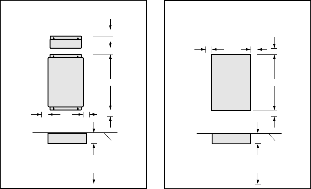
ance requirements for the optional HPFB. Figures
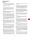
2-2 (Base Key Service Unit) and 2-3 (Base and
Expansion Key Service Unit together) show the
minimum clearance requirements for the standard
FIGURE 2-2
DK16 BASE KEY SERVICE UNIT
MINIMUM CLEARANCE REQUIREMENTS
2"
2"
16.4"
FRONT VIEW
DK8 KEY SERVICE UNIT
AND HPFB CLEARANCE
TOP VIEW
3"
3 FEET
WALL
2"
DK 8 KSU
HPFB
2" 2"10"
2" 2"
2"
2"
18"
FRONT VIEW
12.25"
DK16 BASE KEY SERVICE UNIT CLEARANCE
TOP VIEW
3.5"
3 FEET
WALL
DK 16
BASE KSU
FIGURE 2-1
DK8 KEY SERVICE UNIT AND HPFB
MINIMUM CLEARANCE REQUIREMENTS