


6-11
INSTALLATION-STATION APPARATUS
SECTION 100-816-206
MARCH 1993
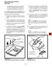
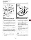
1) Loosen the four captive screws securing the
telephone base (Figure 6-1), and remove the
base.
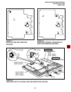
2) Depending on the telephone, refer to Figure
6-7, 6-8, or 6-9 and locate the EX.POW
straps, W101 and W102. Cut these straps.
3) Reinstall the telephone base, and secure it
with its four captive screws.
NOTE:
Refer to Section 100-816-208 for external
AC/DC power supply ordering information
and installation instructions.
3.90 DKT2000 Add-On-Module Installation
3.91 See Paragraph 7 in this chapter.
4 ELECTRONIC TELEPHONE
UPGRADE OPTIONS (DK16 Only)
4.00 This section describes how to upgrade and
configure electronic telephones for features and
options.
4.10 Off-hook Call Announce Upgrade
(HVSU2 or HVSU/HVSI)
4.11 Electronic telephones must be equipped with
either the HVSU2 subassembly or the combined
HVSU and HVSI subassemblies to receive Off-
hook Call Announce (OCA) calls. These tele-
phones also require three-pair wiring to receive
OCA, instead of the standard two-pair. Telephones
making OCA calls do not require an upgrade or
extra wire pair.
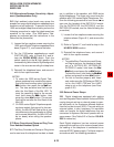
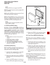
4.12 HVSU2 Upgrade Installation. Install the
HVSU2 in accordance with the following steps:
1) Loosen the four captive screws securing the
telephone base (Figure 6-1), and remove the
base.
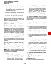
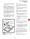
2) Position the HVSU2 on the standoffs inside
the base, and secure with the two provided
screws (Figure 6-12).
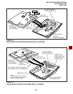
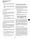
3) Connect the HVSU2 wire plug to the P2
connector on the printed circuit board (PCB)
in the telephone (Figure 6-13).
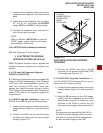
4.13 HVSU/HVSI Upgrade Installation. In-
stall the HVSU/HVSI subassemblies in accor-
dance with the following steps:
1) Loosen the four captive screws securing the
telephone base (Figure 6-1), and remove the
base.
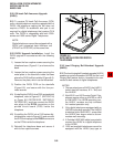
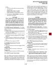
2) Align the P5 connector on the HVSI subas-
sembly with the receptacle on the HVSU
subassembly (Figure 6-14). Apply firm, even
pressure to the PCBs to ensure that the
connectors mate properly (they should click).
NOTE:
Exercise care when assembling the HVSU to
the HVSI to prevent damage to the connector
pins; also, verify that the HVSU is aligned with
the silk-screened image on the HVSI.
TO HVSU
CONNECTOR (P2)
ON MAIN PCB
INSIDE
TELEPHONE
HVSU2
FIGURE 6-12
HVSU2 INSTALLATION FOR ELECTRONIC
TELEPHONES