


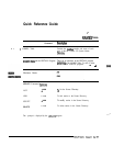
NUMBERING PLAN
T&e
16-l
-
16.1
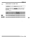
NUMBERING PLAN TABLE FOR MULTI-CABINET
NETWORKING
Multi Cabinet Networking refers to situations where more than one
Toshiba VP System is linked
together behind one
PBX at one location.
-
_
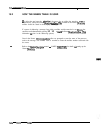
For each cabinet in the
mu&cabinet
network, the NUMBERING PUN Table
d&m-.
l
Location of each system
on
the network
l
Initial digits dialed to reach that location
l
Mailbox length on the co-located cabinet
0
Number of digits to strip (always zero for co&cat&i cabinet entries)
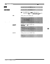
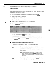
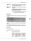
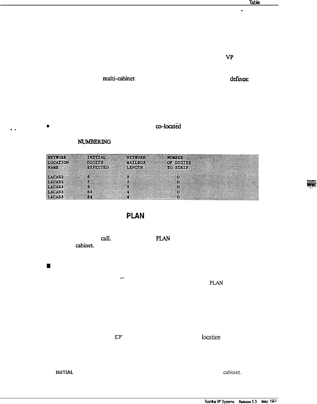
Example of a
NUMBERING
PLAN Table:
n
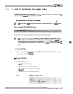
How the NUMBERING PLAN Table is Used
The NUMBERING PLAN Table contains the initial digits dialed by the caller, which determine
where to route the
call
The NUMBERING
PLAN
Table also defines the length of mailboxes
on each
cabiiet.
B
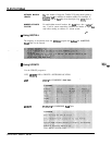
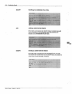
How to Configure the NUMBERING PLAN Table
A maximum of 511 entries may be defined
in the NUMBERING PLAN Table.
NETWORK LOCATION The name of each cabinet on the network. The location name must
NAME
be defined in the LOCATION Table before it can be entered in the
NUMBERING PLAN Table. For co-located systems, the same
location name can be entered multiple times with different initial
digits expected.
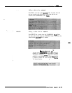
p
In remote networking, Self, as a
locdtion
name, is used to
identify the cabinet currently being configured. Self is not
needed in multi-cabinet networking. It is used only in remote
networking.
iNITlAL
DIGITS Leading digits specific to mailboxes on each
abinet.
Generally,
EXPECTED
either a unique digit or two unique digits are defined.