IMI
66-083
Installa,.
POWER FAILURE STATION
CONNECTIONS
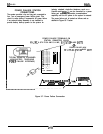
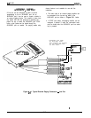
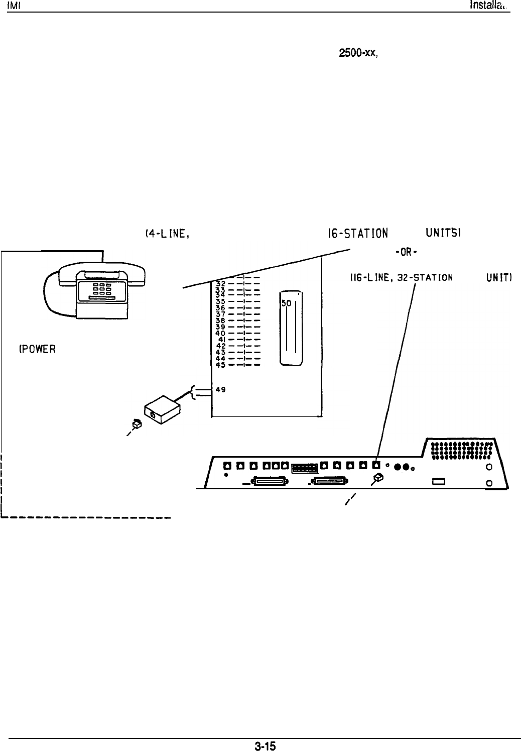
The system provides a tip and ring pair connected to
line 1 as an emergency power failure circuit. This
circuit is active during a commercial AC power failure
if an external battery assembly is not installed to
provide battery back-up power to the system. An
industry standard, single-line telephone, such as a
Comdial model
2500-xx,
can be connected to a power
failure pair and used to provide communications
capability until the AC power to the system is restored.
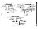
The power failure pair is located as follows and as
detailed in Figure 3-7 below.
POWER FAILURE TERMINALS ON
STATION CONNECTOR BLOCK
t4-LINE,
8-STATION AND 8-LINE,
I6-STATION
BASE
UNITS1
TYPICAL INDUSTRY STANDARD
NON-ELECTRIC TELEPHONE
(POWER
FAILURE INTERFACE)
I
I
I
I
L-----,---mm---,-,,,
25
JO
26
I
.-
46 --l--
47--l--
46 --l--
49
--l--
50 --l--
CLIP TERMINALS
-OR-
POWER FAILURE JACK
lI6-LINE,
32-STATION
BASE
UNIT1
.
.
.
.
.
.
.
.
.
.
.
.
.
.
.
.
.
.
.
.
.
.
.
.
.
.
.
.
.
.
.
.
.
.
.
.
.
.
.
.
.
.
I
.
.
.
.
.
.
0..0...0
•I0LIn0L1~a0rJ~LIo.0,
*
*=*
*=lm
p
l
0
/
/
,---------e----B---d’
Figure 3-7. Power Faliure Connection


