


MERLIN LEGEND Communications System Release 6.1
Installation
555-661-140
Issue 1
August 1998
Installing the Control Unit
Page 2-34
Installing the Modules
Installing Modules
To install modules starting from slot 1 (the first open slot next to the
processor), follow the steps below:
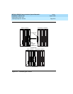
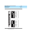
!For each 400EM tie line/trunk module, for jacks numbered 1 through
4 in Figure 2–11, check Form 3c, Incoming Trunks: Tie, for E&M
signaling type.
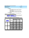
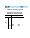
Set the dual in-line packaging (DIP) switches on the front of the 400EM
Tie Trunk module according to the E&M signaling type settings listed in
Table 2-4 on page 2-36
and Table 2-5 on page 2-37 and shown in Fig-
ure 2-11 on page 2-38. The default E&M signal does not require any
adjustments in the DIP switches.
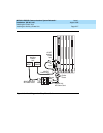
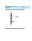
!Remove the protective cover from each module’s gold-finger
connector.
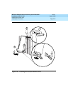
!Lower the hook on top of the module onto the rod on the top of the
carrier in the appropriate slot. See Figure 2-10 on page 2-32
.
!Make sure the connector on the module mates properly with the
connector on the carrier.
!Swing the module into the slot and firmly push the module into the
carrier until it locks into place.
!
CAUTION:
To avoid damage, do not force the module. If the module does not
insert easily, press the bottom rear locking tab, remove the module,
and inspect the module and carrier for damage or obstruction.
If there is no damage and no obstruction, reinsert the module. A
damaged carrier or module must be replaced.
!Repeat Steps 1 through 5 for each module you want to install.