


MERLIN LEGEND Communications System Release 6.1
Installation
555-661-140
Issue 1
August 1998
Connecting the Control Unit to the Network Interface
Page 4-10
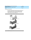
Wiring
!Test the central office trunks for proper connection.
See “Testing Trunks,” later in this chapter, for instructions.
!Label the network interface jacks, control unit module jacks,
termination blocks, and D2R cords.
See “Labeling Trunks,” later in this chapter, for instructions.
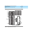
! For each trunk, plug one end of a D2R cord into the designated jack
on the termination block and the other end into the line/trunk jack
on the proper control unit module.
NOTE:
The modular jacks on the termination block are 8-wire jacks. The
D2R cords, which are 6-wire, also plug into the 8-wire jacks.
!
CAUTION:
Do not plug an analog multiline telephone, an MLX
telephone, or anything else that should be plugged into an
extension jack into this wiring field: doing so will busy-out
the trunk.
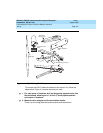
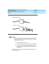
RJ11 and RJ14 Interfaces
RJ11 and RJ14 interfaces are connected to the control unit similarly.
However, note the following differences:
■ RJ11 connects
one
central office trunk per jack.
■ RJ14 connects
two
trunks per jack.
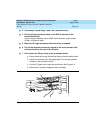
Plug a 267C-type adapter into each RJ14 jack. You need D2R cords for
RJ11 jacks. See Figure 4–5.