


Chapter 1 ( SRS-2100 Overview
Page 1-3
LOOP
TEST
Off On
Line
NOR
PRG
40V DC
TR
+ -
1 2
3 4 5
6
7
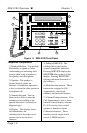
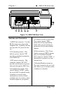
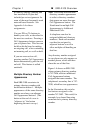
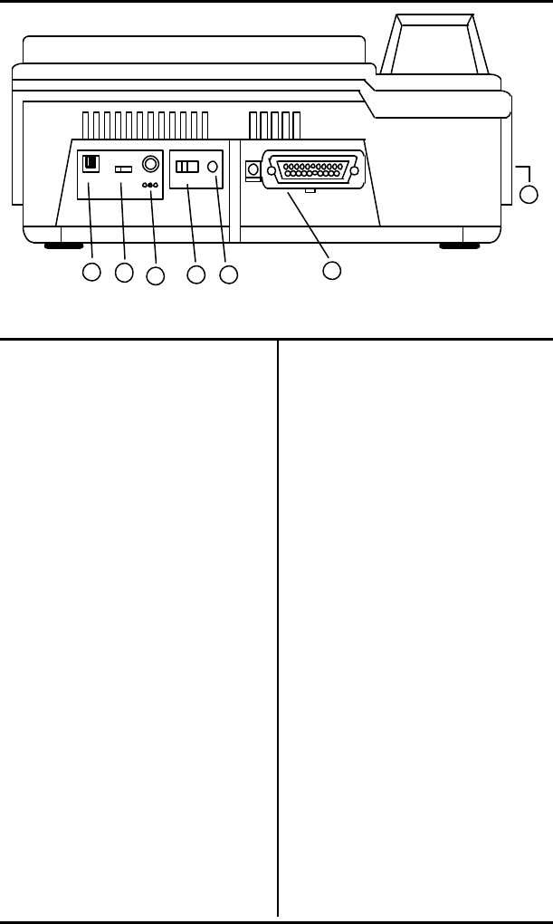
Figure 1-2 SRS-2100 Rear View
Switches and Connectors
1) ISDN line connector. Use this
RJ-45 connector to plug in the
telephone line. Normally, the line
also provides AC power for the
set.
2) Terminating resistor. This
built-in resistor, labeled "TR",
provides a standard termination
to the ISDN line.
3) DC power connector. This
connector, labeled "40 V DC",
provides an alternative to power
delivered through the ISDN line.
4) Loopback test switch. This
switch, labeled "LOOP", places
the set in DATA loopback mode.
Loopback is a test for data
transmission, so this switch is
available only if you have a data
terminal adapter in your phone.
5) Program switch for data setup.
This switch, labeled "PRG",
places the set in programming
mode when you are setting up
parameters for the data terminal
adapter.
6) Data connector. This 25-pin
female connector (DB25) appears
only on voice/data terminals.
This connector, labeled "DTE", is
the interface connector for data
transmission.
7) Handset/Headset connector.
This jack, located on the set's left
side, allows you to connect either
a handset or a headset.