


SRS-2100 Installation ( Appendix B
Page B-2
INSTALLING THE SRS-2100
ISDN equipment may be installed
in a number of configurations. In
most installations, the
supplementary equipment (NT1
and power) is located in a wire
closet in your building. If this is
the case in your installation,
please skip to the section below:
“Connecting to the Network”.
In some installations, the NT1 and
power are located at the user's
desk.
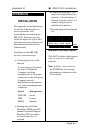
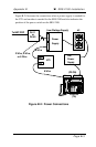
Two drawings are included that
illustrate the connections you
may need to make when the
power and NT1 are located at the
user's desk.
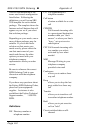
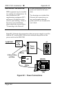
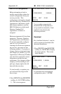
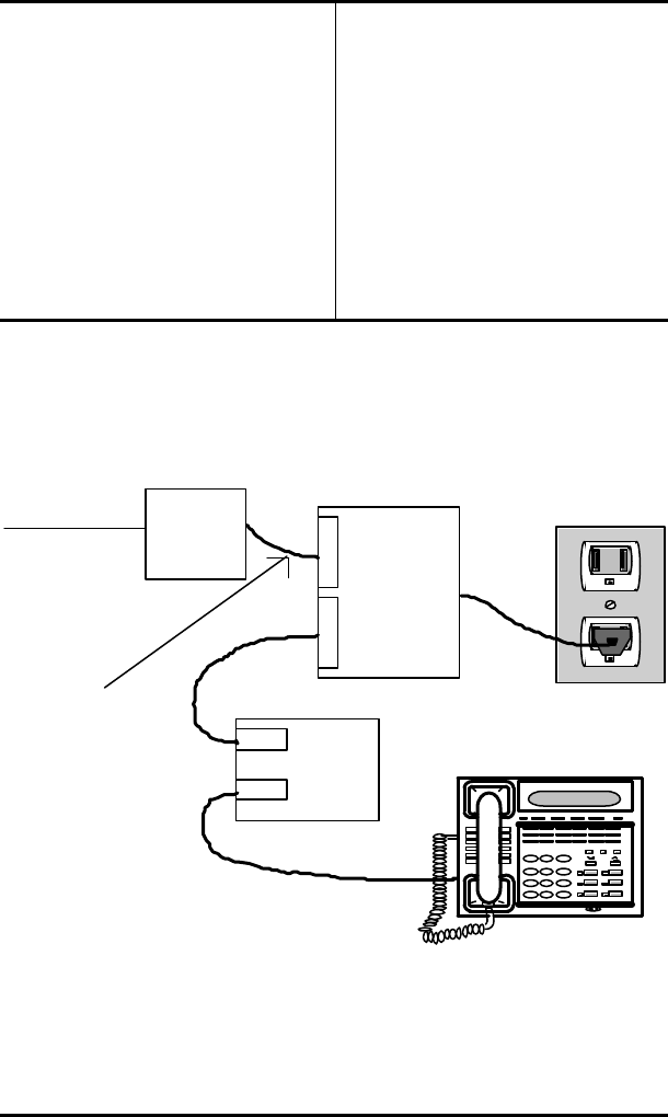
Figure B-1 illustrates the connections when one power supply is used for
both the NT1 and the SRS-2100 and also indicates the position of the
power switch on the SRS-2100.
To NET-POP RJ-11
or
RJ-45
Power
Supply
L
I
N
E
N
T
1
NT1
Line
Term
AC
8 Wire
8 Wire
2 Wire, 4 Wire,
or 8 Wire
(PS OFF)
ISDN Set
(TA)
Figure B-1: Power Connections