


4-28 Issue 2.0 December 1995
Remote Access (Dial-Up) Connections
Connect to Serial Port 2 (COM2) if it is available. If Serial Port 2 (COM2) is not
available, connect to the first available port on the Multi-Port Serial Card.
The following parts are required:
■ Multi-Port Serial Card (if needed and not already installed)
■ 6-position, 6-conductor straight-through modular cord (for connection to
Multi-Port Serial Card only, supplied with Multi-Port Serial Card)
■ DTE 4/6-to-DB-25P Adapter (for connection to Multi-Port Serial Card only,
supplied with Multi-Port Serial Card)
NOTE:
This adapter has slanted sides as shown in Figure 4-15.
■ DB-9S to DB-25P Adapter (for connection to Serial Port 2 on MAP/5 or
COM2 on MAP/40 or MAP/100 only)
■ RS-232 M-F cable (for connection to Serial Port 2 on MAP/5 or to COM2 on
MAP/40 or MAP/100 only)
■ Modem (Paradyne COMSPHERE 3820, includes modular cord and power
supply)
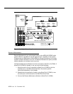
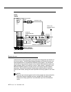
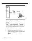
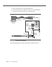
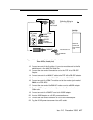
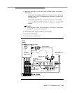
Refer to Figure 4-15. Connect the Intuity Remote Maintenance Modem by
following these steps:
1. To connect to the Intuity system:
— To connect to Serial Port 2 (COM2), connect the small end of the
DB-9P to DB-25S adapter to Serial Port 2 on the MAP/5 or COM1 on
the MAP/40 or MAP/100. Then connect one end of the DB-25 M-F
cable to the large end of the DB-9P to DB-25S adapter.
— To connect to the first available port on the Multi-Port Serial Card,
connect one end of the 6-position, 6-conductor modular cord to the
port. Then connect the other end of the modular cord to the DTE
4/6-to-DB-25P adapter.
2. Connect the other end of the DB-25 M-F cable or the DTE 4/6-to-DB-25P
adapter to the matching connector on the modem.
3. Connect one end of the modular cord supplied with the modem to the jack
marked DIAL on the modem.