


Issue 2.0 December 1995 4-21
The following parts are required:
■ DB-9S to DB-25P Adapter
■ RS-232 M-F cable
■ Modem (Paradyne COMSPHERE 3820, includes modular cord and power
supply)
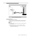
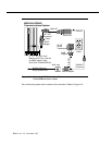
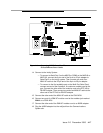
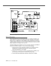
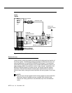
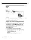
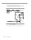
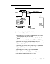
Refer to Figure 4-11. Connect the Intuity Remote Maintenance Modem by
following these steps:
1. Connect the small end of the DB-9S to DB-25P adapter to Serial Port 2 on
the MAP/5 or COM2 on the MAP/40 or MAP/100.
2. Connect the matching end of the DB-25 M-F cable to the large end of the
DB-9S to DB-25P adapter.
3. Connect the other end of the DB-25 M-F cable to the matching connector
on the modem.
4. Connect one end of the modular cord supplied with the modem to the jack
marked DIAL on the modem.
5. Depending on whether or not the MERLIN LEGEND system is equipped
with DID lines:
— If the system does
not
have DID lines, connect the other end of the
modular cord to a RJ11C telephone jack wired to a Loop Start (LS)
line from the CO.
— If the system has DID lines, connect the other end of the modular
cord to a MERLIN LEGEND Tip/Ring port that has an assigned DID
number.
NOTE:
If building wire is used, it must be type 3 UTP or better. The distance
limitation is the same as for a station.
6. Connect the power supply connector to the modem.
7. Plug in the power supply.
8. Turn on power for the modem.