


Technical Product Manual - DCT1900
Product Specifications, Base Stations
2-2
Specs-DCT1900/R8/mw
© 2000-2005
Receiver Radio Specifications
All specifications mentioned here are measured on the RF connector.
Receiver sensitivity : typical -92 dBm with a B.E.R. = 10
-3
at the radio interface
Input compression : better than -30 dBm at -1 dB compression point
Maximum input level : as per PWT
Typical C/I ratio : as per PWT
Typical C/N ratio : as per PWT
Unwanted emissions : as per PWT
Base Station Cable
Signal and power transport : 2 unshielded twisted pairs
Express power transport : 1 optional unshielded pair (should be twisted)
Maximum length : see Tables 2–1 and 2–2.
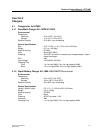
Table 2–1 Maximum Cable Length for Locally Powered Base Stations
* Cable lengths should never exceed the values given in table 2–1, because of data limitations
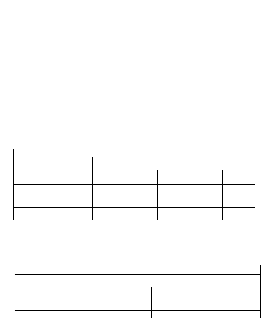
Table 2–2 Maximum Cable Length for Centrally Powered Base Stations
Cable Maximum cable length
Superimposed noise
8 mV/pHz
Superimposed noise
10 mV/pHz
Type Wire size (Æ)
AWG
Capacitance
CLU 11/2 SLU/CLU-S CLU 11/2 SLU/CLU
Twisted pair 26ga 15 pF/ft. 7540 ft. 4920 ft. 6560 ft. 4260 ft.
Twisted pair 24ga 15 pF/ft. 11480 ft. 6880 ft. 9840 ft. 6230 ft.
Twisted pair 22ga 40 pF/ft. 6880 ft. 4260 ft. 5900 ft. 3930 ft.
Double twisted pair
(J–Y (St)Y 2 2 0.6)
22ga 40 pF/ft. 6160 ft. 3930 ft. 4920 ft. 3280 ft.
Maximum Cable Length (feet)
Power Supply Voltage
27.5 V
Power Supply Voltage
42 V
Power Supply Voltage
48 V
Wire size
(∅)
0 EPP 1 EPP 0 EPP 1 EPP 0 EPP 1 EPP
26 awg 418 627 1405 2107 1842 2763
24 awg 627 941 2107 3161 2763 4145*
22 awg 1026 1539 3448* 5172* 4522* 6782*