


Technical Product Manual - DCT1900
Installation Instructions, Modular Cabinet – CPU Cabling
Install-DCT1900/R8/mw 20-3
© 2000-2005
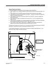
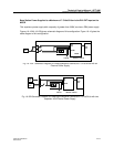
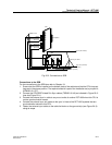
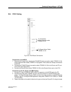
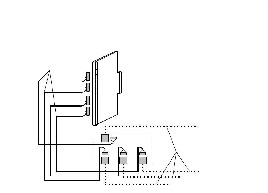
Fig. 20-2 Connections to SDB
Connections to the SDB
For the connections to the SDB also refer to Chapter 18:
1. Ensure that the SDB is installed on the bottom plate of the cabinet and that the CPU strap set-
tings are in the proper position. The required material is part of the installation set, sync port kit
(NTMNB 101 107).
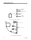
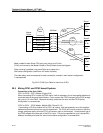
2. Connect the CPU/SDB Twisted Pair Sync cables (TSRNB 101 48) as indicated in Figure 20–2
(see also Figure 20–1).
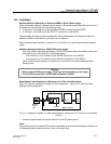
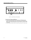
3. Connect the external sync in cable to a sync out outlet of another DCT1900 when this CPU is
not the synchronization master.
4. Connect the external sync out cables to the sync in inlets of the DCT1900 systems that are
synchronization slaves to this CPU.
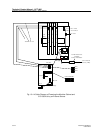
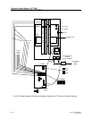
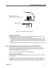
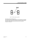
5. Fasten the external sync cables to the cable tie blocks on the ground strip (see Figure 20–3)
using tie wraps.
Sync in
Sync out 1
Sync out 2
Sync out 3
to backplane
SDB
TSRNB 101 48
X6 X5X7
X8
X3
X4
External sync cables
X1
X2
CPU
Sync in (from master)
Sync out 1 (to slave)
Sync out 2 (to slave)
Sync out 3 (to slave)