


Technical Product Manual - DCT1900
Installation Instructions, Digital Trunk Unit (DTU–E1) – REX-BRD0002 or 2/ROFNB 157 13/1
11-2
Install-DCT1900/R8/mw
© 2000-2005
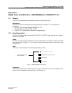
LEDs
Each DTC has its own LEDs:
LED1 Green : Normally on. Power On LED
LED2 Red : Normally off. Watch–dog LED
LED3 Red : Normally off. Board not polled LED
LED4 Red : Normally off. Board Error LED
11.3 Installation
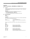
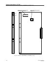
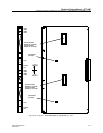
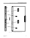
1. Place the DTU–E1 Firmware Set PROMs into the IC sockets as indicated and check the strap
settings (see Figure 11–1).
2. Insert the DTU–E1 into the card guides in the specified board position.
3. Gently push the board into the backplane connector until it locks. Don’t use any force.
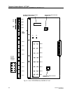
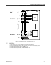
4. Connect the twisted pair cables for cable set AWS1033 to the front of the board.