


Technical Product Manual - DCT1900
Installation Instructions, Modular Cabinet – CPU Cabling
20-2
Install-DCT1900/R8/mw
© 2000-2005
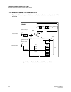
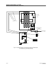
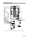
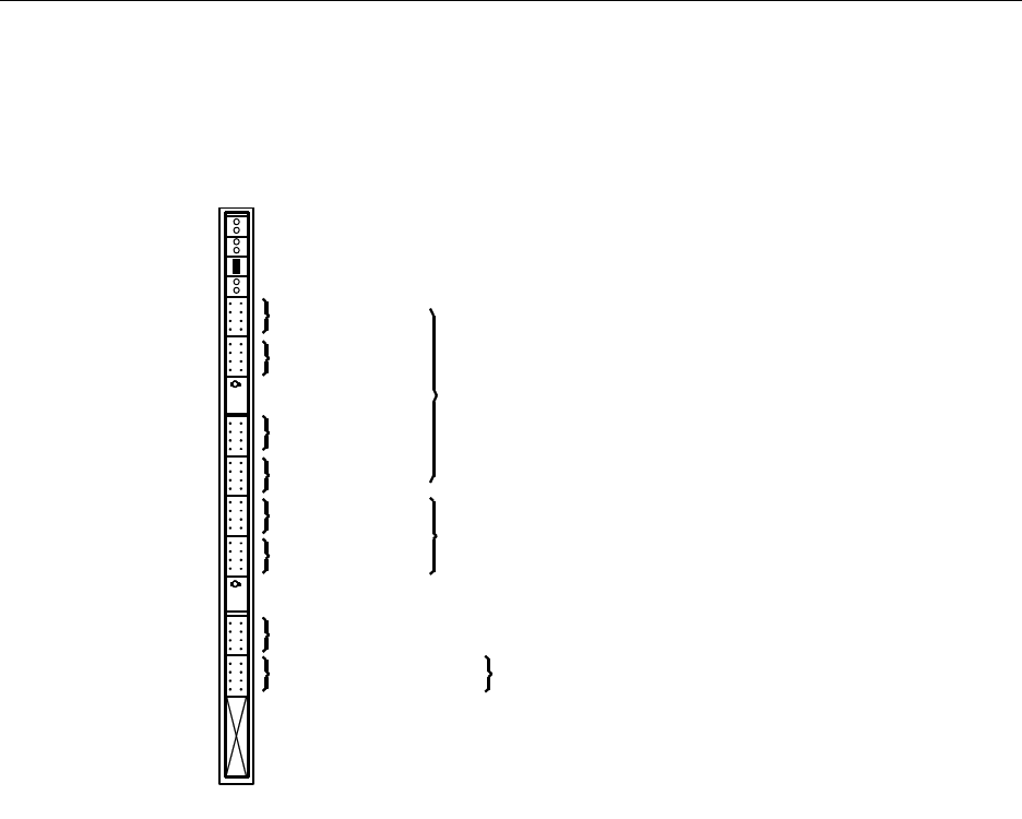
20.2 CPU1 Cabling
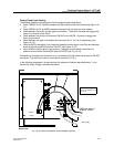
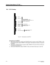
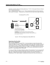
Fig. 20-1 Connections to the CPU1
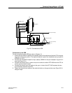
Connections to the MCCB
1. Remove the tie-wrap that is holding the CPU/MCCB serial connection cable (TSRNB 101 26)
and the general alarm cable (TSRNB 101 28) together. Both cables are already connected to
the MCCB.
2. Connect the CPU/MCCB serial connection cable (TSRNB 101 26) to the Printer and PC port
on the CPU (see Figure 20-1).
3. Connect the General Alarm cable (TSRNB 101 28) to the General Alarm port on the CPU.
Printer port
RS232-A
PC port
RS232-B
General Alarm port
To CPU/MCCB
Serial Connection cable
(TSRNB 101 26)
To General Alarm cable
(TSRNB 101 28)
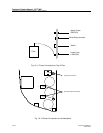
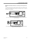
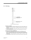
Sync out 1
Sync in
Sync out 2
Sync out 3
To 4x CPU/SDB
Twisted Pair Sync cables
(TSRNB 101 48), refer to Figure 1-2.
Not used
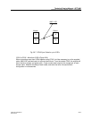
Refer to Figure 20-2