


Technical Product Manual - DCT1900
Installation Instructions, Digital Trunk Unit (DTU-T1, CCS) - REX-BRD0025 or 2/ROFNB 157 13/3
Install-DCT1900/R8/mw 13-1
© 2000-2005
CHAPTER 13
Digital Trunk Unit (DTU-T1, CCS) - REX-BRD0025 or 2/ROFNB 157 13/3
13.1 General
The DTU–T1 provides 46 (23B+D) communication channels via two 1.544Mbit/s links (primary
rate interfaces).
Maintenance
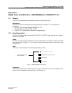
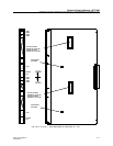
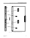
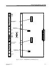
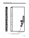
The DTU–T1 has the following field–exchangeable parts (see Figure 13-1 for placement &
orientation):
z DTU–T1 CCS Firmware RYS 105 650
z The DTU–T1 CCS Firmware is pre-installed on the board.
13.2 Board Description
The DTU–T1 Board contains two identical Digital Trunk Circuits (DTC1 and DTC2), each with their
own identical connectors and LEDs.
Cables
The DTU-T1 interfaces via 100 ohm twisted pair cable only (AWS1034).
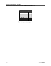
Jumpers
The line length selection can be adjusted with the three jumpers 1, 2 and 3 (see Table 13-1).
Note:
The jumper settings should be 3 O, 2 O and 1 C if the DTC is externally looped back via the
twisted pair connector.
Connectors
The DTU–T1 board has 4 connectors at the front, two for each DTC. Only the twisted pair
connector is used. See Figure 13-1.
LEDs
Each DTC has its own LEDs:
LED1 Green : Normally on. Power On LED
LED2 Red : Normally off. Watch–dog LED (not significant)
LED3 Red : Normally off. Board not polled LED
LED4 Red : Normally off. Board Error LED
13.3 Installation
1. Place the DTU–T1 Firmware PROMs and check the strap setting (see Figure 13-1).
2. Insert the DTU–T1 into the card guide in the specified board position.
3. Gently push the board into the backplane connector until it locks. Don’t use any force.
4. Connect the cable, AWS1034 to the front of the board.