


Technical Product Manual - DCT1900
Maintenance, Test and Maintenance Software
Maint-DCT1900/R8/mw 2-3
© 2000-2005
z An additional fault report will be written in a third table called "Service" table.
z A general alarm is raised.
z An alarm message is sent to the MS (Mobility only).
z A warning is generated by the CSMW software when running.
Note:
Red LED5 on the CPU board is on if there are messages in the "Info", "Fault" or "Service" tables
that have not been read by means of the CSMW software.
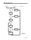
2.2.1 Diagnostics
After T&M has concluded that the message is not an info but a fault message, T&M starts to
decode, locate and verify the fault. This is done by the diagnostics module. After verification, T&M
will isolate the faulty circuit to prevent usage by the system. This is done by changing its status
temporarily to Test Mode (TME). When the fault cannot be verified, i.e. the fault cannot be found,
the fault message in the Fault table will be completed with the status code C (cleared). This could
indicate the occurrence of an intermittent fault.
2.2.2 Fault Counters
After verification of the fault, T&M knows exactly what type of fault occurred and where. A fault
counter for this fault will be incremented. When the fault counter exceeds its threshold value, no
further measures are taken, but immediately a GA will be activated with fault code 3 in the service
table. The function of the fault counter is to count faults that can be cleared by maintenance, see
Paragraph 2.2.3, but continue to re–appear, i.e. intermittent faults. When too many of these
"intermittent faults" are counted within a specific time limit, an alarm shall be raised. The fault
counter is halved every 24 hours to avoid generation of alarms when intermittent faults only occur
occasionally.