


Technical Product Manual - DCT1900
Installation Instructions, Modular Cabinet – Power Cabling
Install-DCT1900/R8/mw 19-1
© 2000-2005
CHAPTER 19
Modular Cabinet – Power Cabling
19.1 Introduction
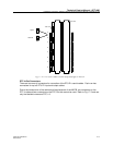
This chapter describes the installation of the power cables in two different versions of the Modular
Cabinet. The installation depends on the number of external -48Vdc power supplies and on how
the Base Stations are powered.
WARNING
Disconnect or switch off all power supply sources before servicing any power
supply circuit.
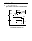
19.2 Modular Cabinet - BDVNB 101 01/3 (R2, R3)
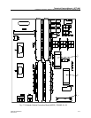
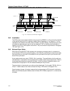
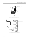
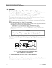
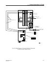
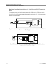
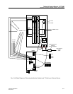
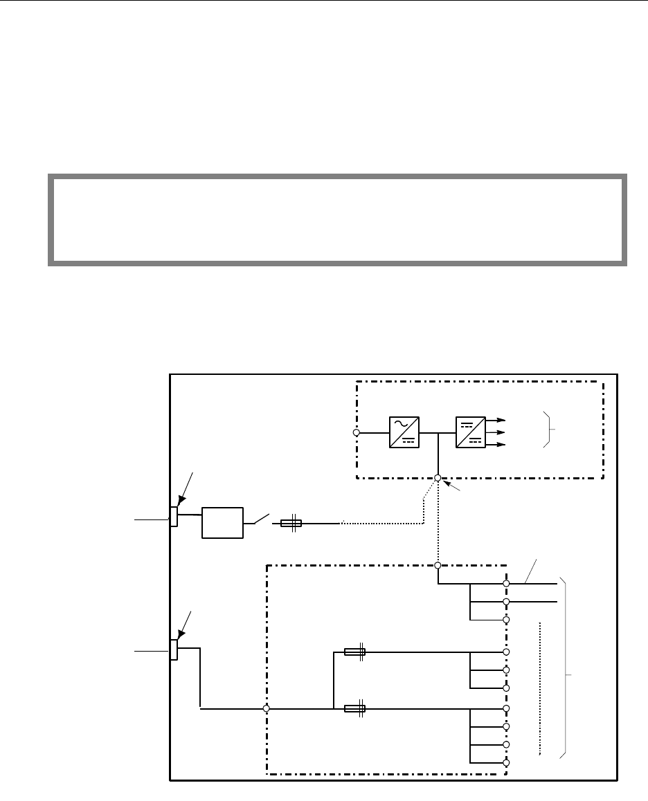
Fig. 19–1 shows the power distribution in a Modular Cabinet powered by external -48Vdc supplies.
Fig. 19-1 Power Distribution Powered by External -48Vdc
Mains
filter
+ 5 V
+ 12 V
* 12 V
To
System
Boards
BACKPLANE
To
CLUs
PW1
PW2
PW3
PW4
PW5
PW6
PW3
MCCB
MODULAR
CABINET
TSRNB
101 33
X112, X113
PW-EXT
TRENB
101 03
PW-BP
TRENB
101 05
or
X102
Piggy-back
FASTON
Terminal
Block A
(see Figure 16-2)
15 A
15 A
15 A
48 Vdc
PW1
PW2
PW7
F1
F2
External 48 Vdc
Terminal
Block B (see
Figure 16-2)
Power Supplies
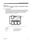
TERMINAL BLOCK A
(S
EE FIG. 19-2)
TERMINAL BLOCK B
(S
EE FIG. 19-2)
External -48Vdc
External -48Vdc