


Technical Product Manual - DCT1900
Installation Instructions, Base Station – KRC 101 1371
16-4
Install-DCT1900/R8/mw
© 2000-2005
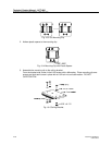
The cable set, NTM/TSRNB 101 29, that connects the CLU/SLU to the MDF brings out the three
pairs mentioned above: SC0, SC1, and EPP. Refer to Fig. 21-3, 66 Block Diagram in Chapter 21
for the pin out of the 66 Block where this cable terminates.
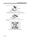
A minimum of -21V DC is required at the Base Station for it to operate. When a Base Station is
located too far away from the Radio Exchange to be powered by the Radio Exchange, then power
can be provided by a local -48V power supply or an AC to 48V DC adaptor. The power supply or
adapter should be placed in the last Intermediate Distribution Frame before the Base Station.
Hook the output of the power supply/adapter to the EPP wires going to the Base Station; DO NOT
connect the EPP wires at the Radio Exchange. Only the two data pairs should go from the Radio
Exchange to the Base Station in this situation. The EPP wires are picked up in the last
Intermediate Distribution Frame where the Base Station’s power source is located.
16.3 Base Station Cable Delay Measurement
The cable delay in each of the cable pairs going to every Base Station must be measured in order
to program the Base Station delays into the system at initialization time. This is necessary in order
to synchronize all Base Stations in the system.
Base Station cable delay may be measured by two methods, ADM or measurement with a TDR
(Time Domain Reflectometer).
ADM, or Automatic cable Delay Measurement, is a feature where the CPU automatically
measures the delay in the cable hooked up to a Base Station. Beginning with the hardware and
software releases listed below, the DCT1900 system can automatically determine the correct Base
Station cable delay. This means that it is no longer mandatory to have a TDR (Time Domain
Reflectometer) on each and every job site to measure the cable delays.
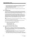
Table 16-2 Minimum Release Requirements to Support ADM
Note:
ADM will not be supported if the system is not comprized of the listed minimum release levels. The
Automatic delay measurement does not work with the CLU boards (REX-BRD0014 or ROFNB 157
11 or ROFNB 157 11/2)
Item Hardware PN Rev Firmware/Software Application Firmware PN Rev
CPU1 REX-BRD0004 R1A DCT1900 Firmware Mobility RYS 105 447 R2A
DCT1900 Firmware Standalone RYS 105 657 R2A
CPU2 REX-BRD9033 R1A DCT1900 Firmware Standalone
CPU2 REX-BRD9034 R1A DCT1900 Firmware Mobility
SLU REX-BRD0015 R3B CLU-S Board Controller MOB & SA RYSNB 101 19 R2A
CLU-S REX-BRD0016 R3A CLU-S Board Controller MOB & SA RYSNB 101 19 R2A
CSM NTM 201 2087 R2B Unlicensed Standalone LZY 213 1031 R2B
CSM NTM 201 1813 R2B Unlicensed Mobility LZY 213 903 R2A
CSMW REX-MCT9023 R3C UTAM MOB & SA
CSMW REX-MCT9022 R3C International MOB & SA