


Technical Product Manual - DCT1900
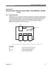
Installation Instructions, Synchronization Distribution Board (SDB) – REX-BRD0006 or ROANB 101 38
Install-DCT1900/R8/mw 18-3
© 2000-2005
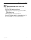
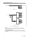
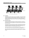
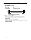
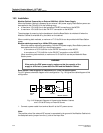
External Sync Cable (TSR 951 284)
Cable length : 20 ft.
Wires : 6 conductor shielded flat cable
Working Voltage : 300V
Connector - System/Sync Port : 6 pin shielded RJ 12 connector
Connector - Modem : 6 pin shielded RJ 12 connector
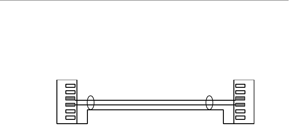
Figure 18–3 Wiring Diagram External Sync Cable
18.4 Sync Input Cable Delay Measurement
The external sync input cable delay must be measured in order to input the system
synchronization delay into the system at initialization. The system synchronization delay
compensates for the delay introduced by the cable. The external sync input cable delay is
measured as follows:
1. Make sure that the other end of the external sync input cable is not connected.
2. Connect a TDR to the terminals 3 and 4 on this end.
3. Measure the cable delay. The resulting value must have an accuracy of 50ns (corresponding
to 16ft. – 33ft.).
4. Note the cable delay value.
6
5
4
3
2
1
1
2
3
4
5
6
GND(shield)
A
B
SYNC
OUT
SYNC
IN