


Technical Product Manual - DCT1900
Installation Instructions, Modular Cabinet – Power Cabling
19-2
Install-DCT1900/R8/mw
© 2000-2005
Factory Fitted Power Cabling
The Modular Cabinet is delivered with the following powering cables fitted:
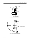
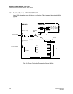
z Cable TRENB 101 02 (#190248) between the filter and the fuse holders (see Fig. 19–3).
z Cable TRENB 101 04 (#190250) between the switch and the two fuse holders.
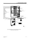
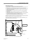
z Cable TRENB 101 05 (#190251)between the switch and connector X112, X113 on the
backplane (see Fig. 19–4). The end of the cable with the piggy–back faston is connected to
the switch.
z Cable TRENB 101 03 (#190249)between connectors X112/X113 and connector PW–BP on
the MCCB.
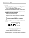
z Cable #190253 (red cable) in two locations: between terminal block A and filter and between
terminal block B and MCCB terminal PW-BP (see Fig. 19-2).
z Cable #190254 (black cable) in two locations: between terminal block A and filter and
between terminal block B and MCCB terminal PW-EXT (see Fig. 19-2).
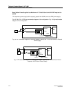
All cables are connected with the red wires (+) connected at the left–hand side, except for the PW-
EXT connection. The red wire of cable TRENB 101 03 is connected to connector X112(+).
In the following paragraphs it is assumed that the cables are fitted as described above. If you
altered the wiring, change it as described above.
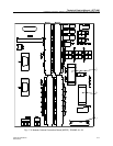
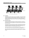
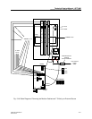
Fig. 19–2 Power Connection to the Modular Cabinet
Red
Black
MCCB
+
|
Red
Black
Additional wires to external
-48V supply
L
+
Red
Black
_
B
A
+
_
-48V supply
.
Warning
Torque the terminal screws
to 7 in./lb.
Additional wires to external
-
+
-48Vsupply
-
+