


Technical Product Manual - DCT1900
System Description, Hardware Building Blocks
System-DCT1900/R8/mw 3-1
© 2000-2005
CHAPTER 3
Hardware Building Blocks
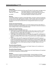
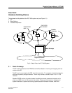
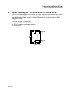
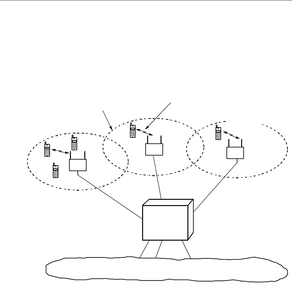
The hardware building blocks of the DCT1900 system are (see Figure 3-1)
z RE
z Base Stations
z Portable Telephones
Fig. 3-1 Basic Parts of a DCT1900 System
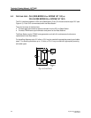
3.1 Radio Exchange
The RE interfaces between the PBX/MS and the Base Stations. Incoming and outgoing calls are
routed via the RE.
The RE may be connected to the PBX via an E1 connection, T1 connection, standard analog two–
wire lines or possibly a digital interface. The RE may connect to the MS via an E1 or T1 CCS
interface.
Standard RS232 ports on the cabinet make it possible to connect a personal computer and a
printer or a SMS server (in SA mode) to the system. The personal computer is necessary for
system initialization, system fault tracing, system statistics information retrieval, and Short
Radio Exchange
Telephone Network
Base
Station
Portable
Telephone
Covered Area
(Cell)
PWT/PWT(E)
air interface