


Technical Product Manual - DCT1900
Installation Instructions, Modular Cabinet – CPU Cabling
Install-DCT1900/R8/mw 20-7
© 2000-2005
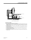
20.4 CPU2 Cabling
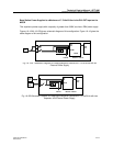
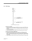
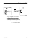
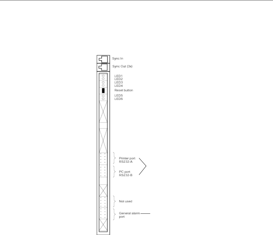
Fig. 20-6 CPU2 Board Connections
Connections to the MCCB
1. Remove the tie-wrap that is holding the CPU/MCCB serial connection cable (TSRNB 101 26)
and the General Alarm cable (TSRNB 101 28) together. Both cables are already connected to
the MCCB.
2. Connect the CPU/MCCB serial connection cable (TSRNB 101 26) to the Printer and PC port
on the CPU (see Figure 20-6).
3. Connect the General Alarm cable (TSRNB 101 28) to the General Alarm port on the CPU.
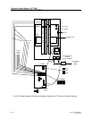
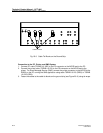
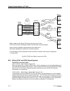
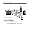
Connection to the PC, Printer, and SMS System
1. Connect PC cable (TSRNB 101 22D) to the PC connector on the MCCB and to the PC.
2. Connect the printer cable (TSRNB 101 23) to the PR connector on the MCCB and to the
printer. For Short Message Service (SMS), connect the printer connector on the MCCB to the
RS232 on the PC running the SMS application using cable TSRNB 101 23 (DB25) or TSRNB
101 22D (DB9).
3. Fasten the cables to the cable tie blocks on the ground strip (see Figure 20–3) using tie wraps.
To CPU/MCCB
serial connection cable
TSRNB 101 26
To General Alarm Cable
TSRNB 101 28