


Technical Product Manual - DCT1900
Installation Instructions, Modular Cabinet – CPU Cabling
Install-DCT1900/R8/mw 20-11
© 2000-2005
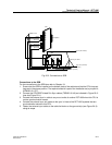
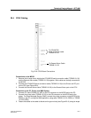
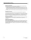
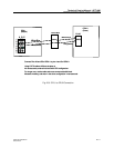
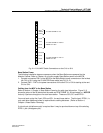
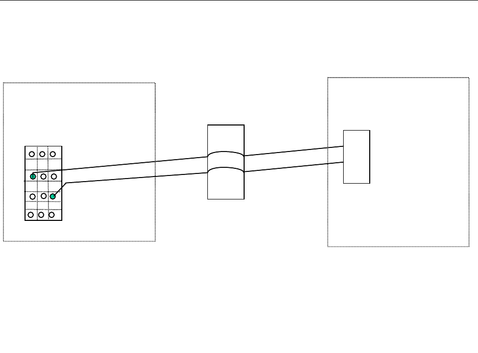
Fig. 20-9 CPU1 to CPU2 Connection
White/Blue
Blue/White
CPU 1
(Master)
CPU 2
(Slave)
RJ-45
4
5
INPUT
Connect Pins A3 and C5 of CPU 1 to pins 4 and 5 of CPU 2.
Using CAT 5 cable at 25 feet, the delay is
40 nanoseconds, entered into the Slave CPU configuration.
For longer runs, cut the cable and cross-connect at the 66 block.
Measure the delay, and enter in the slave configuration in nanoseconds.
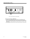
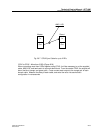
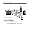
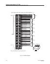
A B C
1
2
3
4
5
6
7
Punch Block
White/Orange
Orange/White
White/Blue
Blue/White
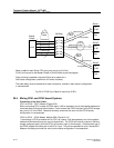
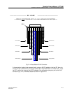
CPU 1
(Master)
CPU 2
(Slave)
RJ-45
4
5
INPUT
Connect Pins A3 and C5 of CPU 1 to pins 4 and 5 of CPU 2.
Using CAT 5 cable at 25 feet, the delay is
40 nanoseconds, entered into the Slave CPU configuration.
For longer runs, cut the cable and cross-connect at the 66 block.
Measure the delay, and enter in the slave configuration in nanoseconds.
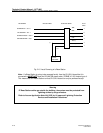
A B C
1
2
3
4
5
6
7
Punch Block
White/Orange
Orange/White