


Technical Product Manual - DCT1900
Installation Instructions, Modular Cabinet – LTU Cabling
23-4 Install-DCT1900/R8/mw
© 2000-2005
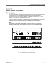
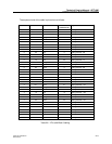
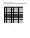
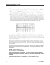
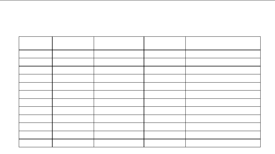
Table 23-1 LTU to 66 Block Cabling (cont.)
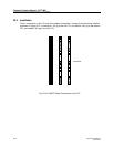
Analog channel 1 tip/ring will appear at the top of the 66 Block. Analog channel 24 tip/ring will
appear on the second to the last pair of the punch down clips at the bottom of the Block. Pair 25 is
not used and is not connected.
Note:
To meet the EMC requirements, the cable should never be cut to a length shorter than 8.2 ft.
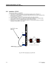
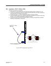
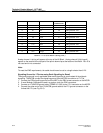
Signalling Ground for LTU when using Earth Signalling for Recall
The signalling ground is only applicable when earth signalling is used instead of timed break
signalling. The MCCB connect the signalling ground from the PBX to maximum of 7 LTUs.
1. Connect the PBX signalling ground from the MDF to the PBX screw connector on the MCCB.
2. If more Modular Cabinets are used in a system, chain the PBX connectors.
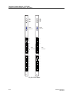
3. Connect an LTU/MCCB ground cable (TSRNB 101 035) to the LTU1 connector on the MCCB.
4. Connect the other end of the LTU/MCCB ground cable to the LTU ground connector on the
furthest left LTU (see Fig. 23-2).
Connector Cable Pair-In Wire Color 25 Pair
Connector Pin
Signal Name
5 7-5 Red 44 Analog Channel - 19T
5 7-6 Orange 19 Analog Channel -19R
5 8-1 Red 45 Analog Channel - 20T
5 8-2 Green 20 Analog Channel - 20R
6 9-5 Red 46 Analog Channel - 21T
6 9-6 Brown 21 Analog Channel - 21R
6 10-1 Red 47 Analog Channel - 22T
6 10-2 Gray 22 Analog Channel - 22R
6 11-5 Black 48 Analog Channel - 23T
6 11-6 Blue 23 Analog Channel - 23R
6 12-1 Black 49 Analog Channel -24T
6 12-2 Orange 24 Analog Channel -24R