


Technical Product Manual - DCT1900
Configuration Directions, Base Station Powering
4-4
Config-DCT1900/R8/mw
© 2000-2005
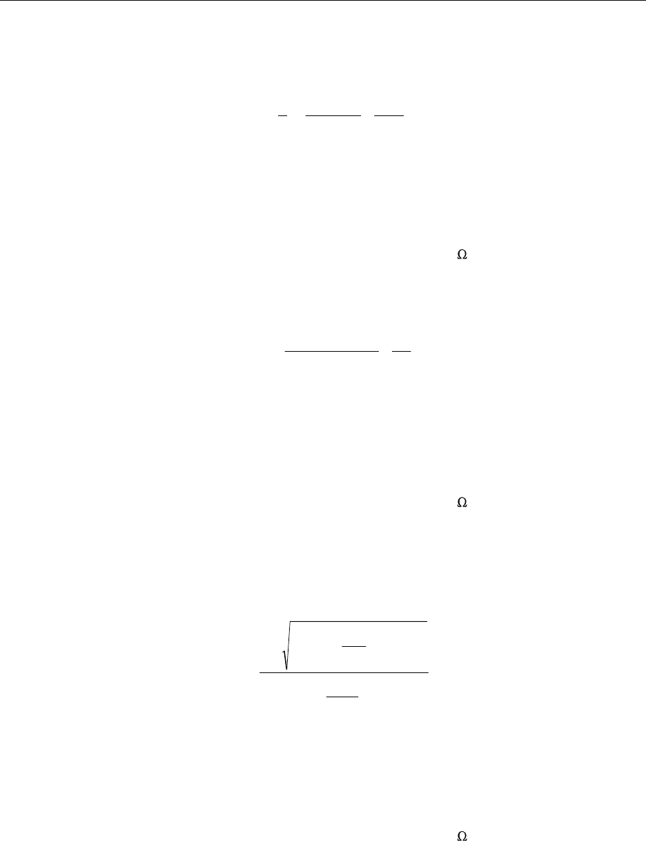
where:
n = number of twisted pairs (when using data pairs only: n=2)
U = power supply voltage
P
Base
= worst case power consumption of Base Station = 7.5W
R
tp
= resistance of twisted pair per meter (double value of single wire)
R = dc losses in filters, transformers and connectors = 1
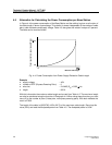
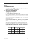
If the supply voltage is 42 Volts or lower, the following formula must be used to calculate to the
power limited lengths:
where:
n = number of twisted pairs (when using data pairs only: n=2)
U = power supply voltage
U
min
= minimum input voltage of Base Station = 21V
P
Base
= worst case power consumption of Base Station = 7.5W
R
tp
= resistance of twisted pair per meter (double value of single wire)
R = dc losses in filters, transformers and connectors = 1
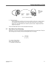
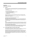
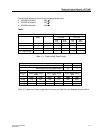
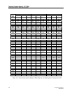
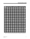
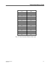
Tables 4-3 and 4-4 give the power consumed by the Base Stations and their cables for different
supply voltages. The consumed power ranges from about 7.5W for zero length cables to 15W
maximum cable lengths (given in Table 4–2). The consumed power has been calculated using the
following formula:
where:
n = number of twisted pairs (when using data pairs only: n=2)
U = power supply voltage
P
Base
= worst case power consumption of Base Station = 7.5W
R
tp
= resistance of twisted pair per meter (double value of single wire)
R = dc losses in filters, transformers and connectors = 1
l = length of the cable
⎟
⎟
⎠
⎞
⎜
⎜
⎝
⎛
×
−
×
×=
tptpBase
R
R
RP
Un
l
4
4
2
max
⎟
⎟
⎠
⎞
⎜
⎜
⎝
⎛
+
×
×
×
⎟
⎟
⎠
⎞
⎜
⎜
⎝
⎛
+×−−
×=
R
n
Rl
PR
n
Rl
UU
UP
tp
Base
tp
2
´
4
2
(
)
⎟
⎟
⎠
⎞
⎜
⎜
⎝
⎛
−
×
−×
×=
tptpBase
R
R
RP
UUU
nl
minmin
max