


Technical Product Manual - DCT1900
Installation Instructions, Cell Link Unit (CLU) – REX-BRD0014 or ROFNB 157 11/2
Install-DCT1900/R8/mw 7-1
© 2000-2005
CHAPTER 7
Cell Link Unit (CLU) – REX-BRD0014 or ROFNB 157 11/2
7.1 General
The CLU is used to control up to 8 Base Stations via twisted pair cables with a maximum length of
2.2 miles.
Maintenance
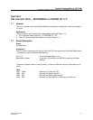
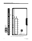
The CLU contains the following field–exchangeable parts (see Figure 7–1):
z CLU Firmware, Board Controller - RYT/ROFNB 157 11/2
z Two 1 AT fuses for each Base Station circuit (see Figure 7–1)
7.2 Board Description
Straps
Not applicable.
Connectors
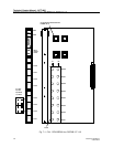
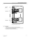
The CLU has 4 connectors at the front by which the CLCs are connected to the Base Stations and
1 connector for input of the Base Station power:
CLC 1–8 : To connect Base Station 1 to 8.
Base Station Power : To connect -48 Volts from the MCCB for powering the Base
Stations.
The power connector does not have a polarity. It makes no difference which pin becomes plus or
minus.
LEDs
LED1 Green : Normally on. Power On LED
LED2 Red : Normally off. Watch–dog LED
LED3 Red : Normally off. Board not polled LED
LED4 Red : Normally off. Base Station in NEW state or board error