


Technical Product Manual - DCT1900
Installation Instructions, Modular Cabinet – CPU Cabling
20-10
Install-DCT1900/R8/mw
© 2000-2005
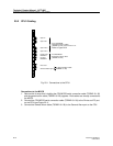
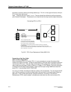
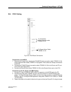
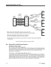
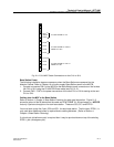
Fig. 20-8 CPU2 Sync Cable for more than 2 REs
20.5 Mixing CPU1 and CPU2 based Systems
Connection of the Sync Cable
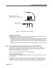
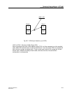
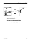
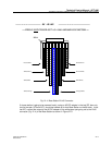
CPU1 to CPU2 - CPU 1 Master (Figure 20-9)
When connecting CPU1 master to CPU2 slave, it will be necessary to cut the supplied cables and
terminate them at the punch-down blocks. Cross connect the CPU1 blue pair to the CPU2 orange
pair, pins 4 & 5 in the RJ45. Measure the delay, and enter the value into the CPU2 (slave)
configuration in nanoseconds.
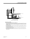
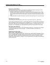
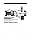
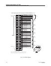
CPU2 to CPU1 - CPU2 Master, Multiple REs (Figure 20-10)
If connecting a CPU2 as master with a CPU1 as a slave, it will be necessary to cut the supplied
cables and terminate them at on a punch down block. The CPU2 will have an output on the blue,
orange, and green pairs, while the CPU1 will have an input on the blue pair. Cross connect one of
the CPU2 outputs to the blue pair of the CPU1 input. This can be repeated for up to 3 slaves REs.
Measure the delay and enter the value into the slave configuration in nanoseconds.
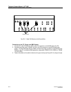
Master
Output
Slave 3
Out
In
RJ-45
Slave 2
Out
Make a cable for each Slave CPU using only pins 4 and 5 of the
RJ-45, and connect to the Master Output on the 66 block as per the diagram.
Daisy chaining is possible using each Slave as a master for a
Sub-cluster configuration (maximum of 2 levels of slaves).
The cable delay must be measured for each connection, entered in each slave’s configuration
in nanoseconds.
Slave 1
Out
In
RJ-45
66 Block
1
2
4
5
7
8
RJ-45
In
RJ-45
4
5
4
5
CAT 5
Cable
CAT 5
Cable
CAT 5
Cable
CAT 5
Cable
5
4
White/Blue
Blue/White
White/Orange
Orange/White
White/Green
Green/White
White/Orange
Orange/White
White/Orange
Orange/White
White/Orange
Orange/White