


Technical Product Manual - DCT1900
Installation Instructions, Synchronization Distribution Board (SDB) – REX-BRD0006 or ROANB 101 38
Install-DCT1900/R8/mw 18-1
© 2000-2005
CHAPTER 18
Synchronization Distribution Board (SDB) – REX-BRD0006 or ROANB
101 38
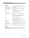
18.1 Board Description
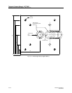
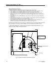
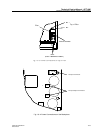
The SDB (see Fig. 18–1) if installed is located on the bottom plate of the Modular Cabinet near the
MCCB and allows the connection of one input and three output synchronization signals to the CPU
via shielded twisted pairs cables. The synchronization signals are required to achieve PWT air
interface synchronization between systems to allow seamless inter system handovers. An
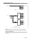
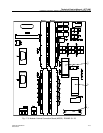
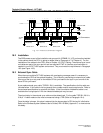
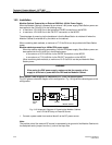
electrical schematic diagram is shown in Fig. 18–2. This board is not factory installed.
Note: Refer to Chapter 20 for CPU2 synchronization.
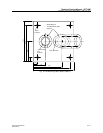
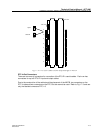
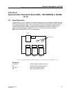
Fig. 18-1 Synchronization Distribution Board - REX-BRD0006 or ROANB 101 38
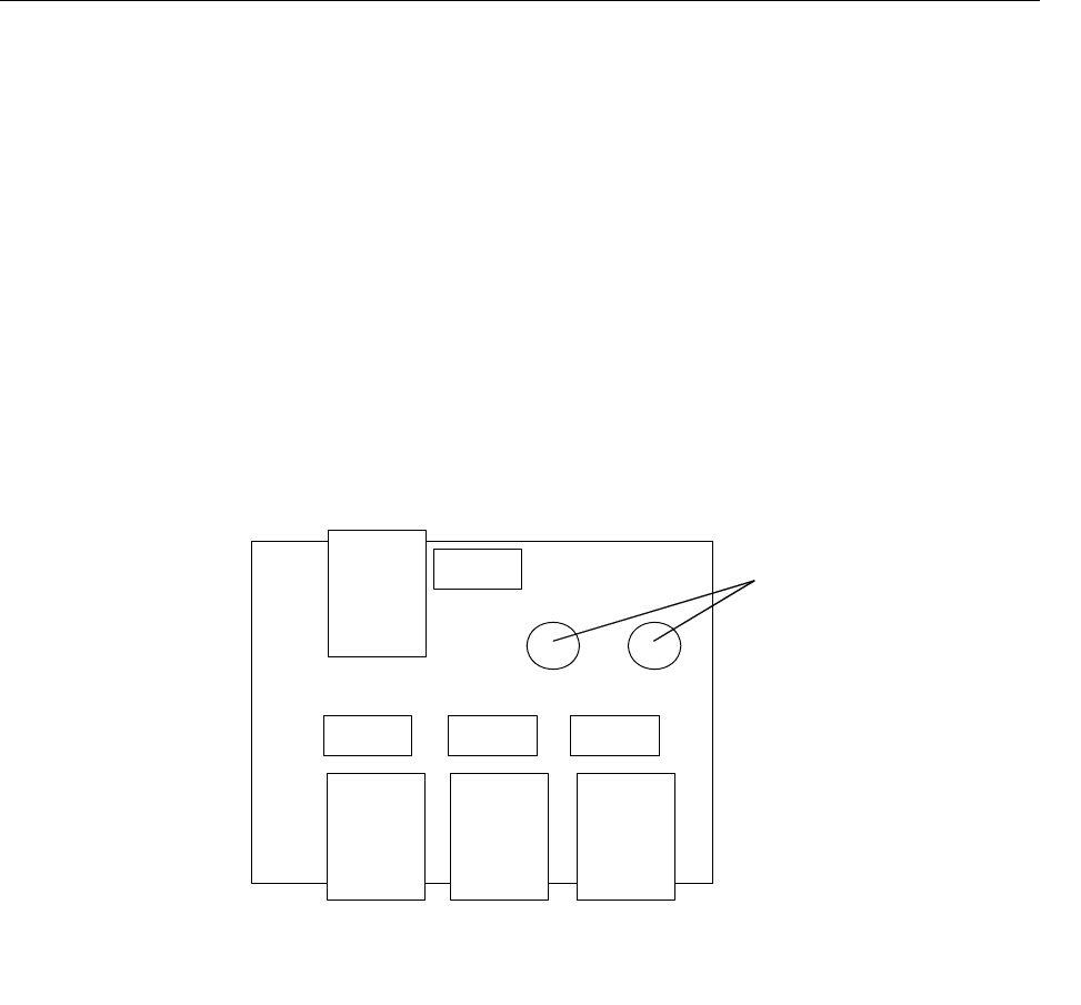
Connectors
X1, X2, X3 : External cable connection sync out.
X4 : External cable connection sync in.
X5, X6, X7 : Sync out connection to CPU.
X8 : Sync in connection to CPU.
X8
X7 X6 X5
SYNC
IN
SYNC
OUT 1
SYNC
OUT 2
SYNC
OUT 3
X4
X3 X2 X1
Screw holes