


Technical Product Manual - DCT1900
Installation Instructions, Modular Cabinet – CPU Cabling
Install-DCT1900/R8/mw 20-5
© 2000-2005
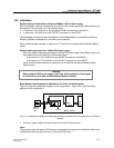
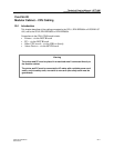
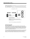
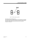
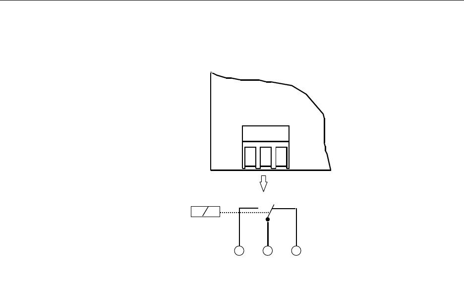
Fig. 20-4 General Alarm Connector (MCCB)
Connection to Alarm Device
The General Alarm relay is normally activated when the Modular Cabinet is switched on. If the
CPU generates a general alarm, the alarm relay is deactivated.
1. Connect an alarm device to the GA–OUT connector on the MCCB (see Figure 20–4). When
the alarm device needs to make contact, connect the alarm device between contacts 1 and 2.
When the alarm device needs to break contact, connect the alarm device between contacts 2
and 3.
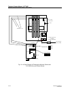
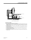
2. Fasten the cable to the cable tie blocks on the ground strip (see Figure 20–3) using a tie wrap.
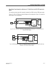
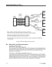
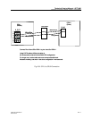
20.3 Synchronization Data Board (SDB) replacement Cable (AWS1154)
The SDB and its attendant cables have been replaced with a simpler, easier to install cable
assembly. The cable assembly connects directly to the front of the CPU1 board. No internal
cables or SDB are required when using this cable.
The part number for this cable is AWS1153 and it is a 25 feet long.
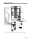
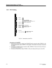
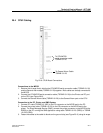
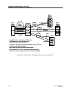
CPU1 Sync Port Pin Connections
The CPU1 board uses a modular type plug for connection to the Sync In and Sync Out connectors.
(see Figure 20-5).
The connector pins are arranged by column and row. There are 3 columns on the connector,
designated A, B, and C. There are seven rows of pins numbered 1-7. To identify the pins, while
holding the connector as if to plug it into the board, the part number marking (RNV 304 002)
GA-OUT
Contact rating: 10VA (peak)
Switching max: 200Vdc or 141Vac
Switching current max: 0.75Adc or 0.53Aac
Relay is activated
when there is
no
alarm
12
3
12
3
3
3